

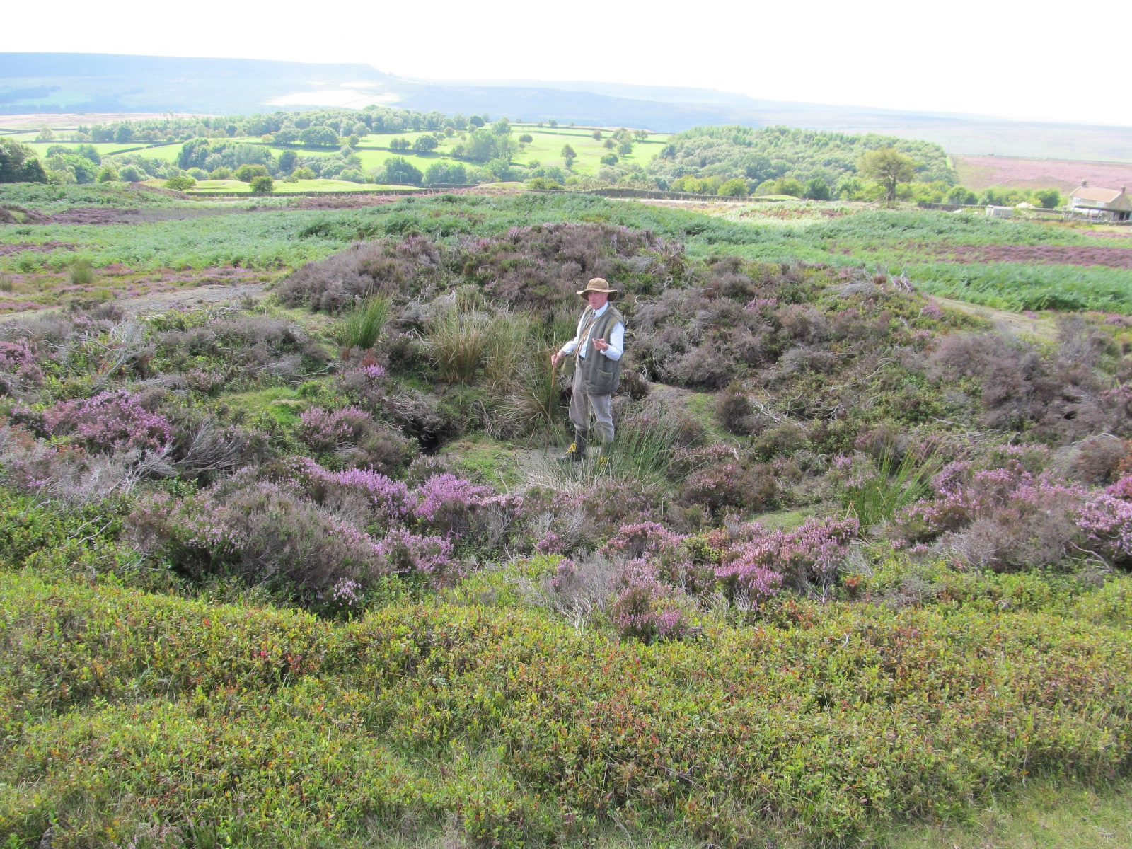
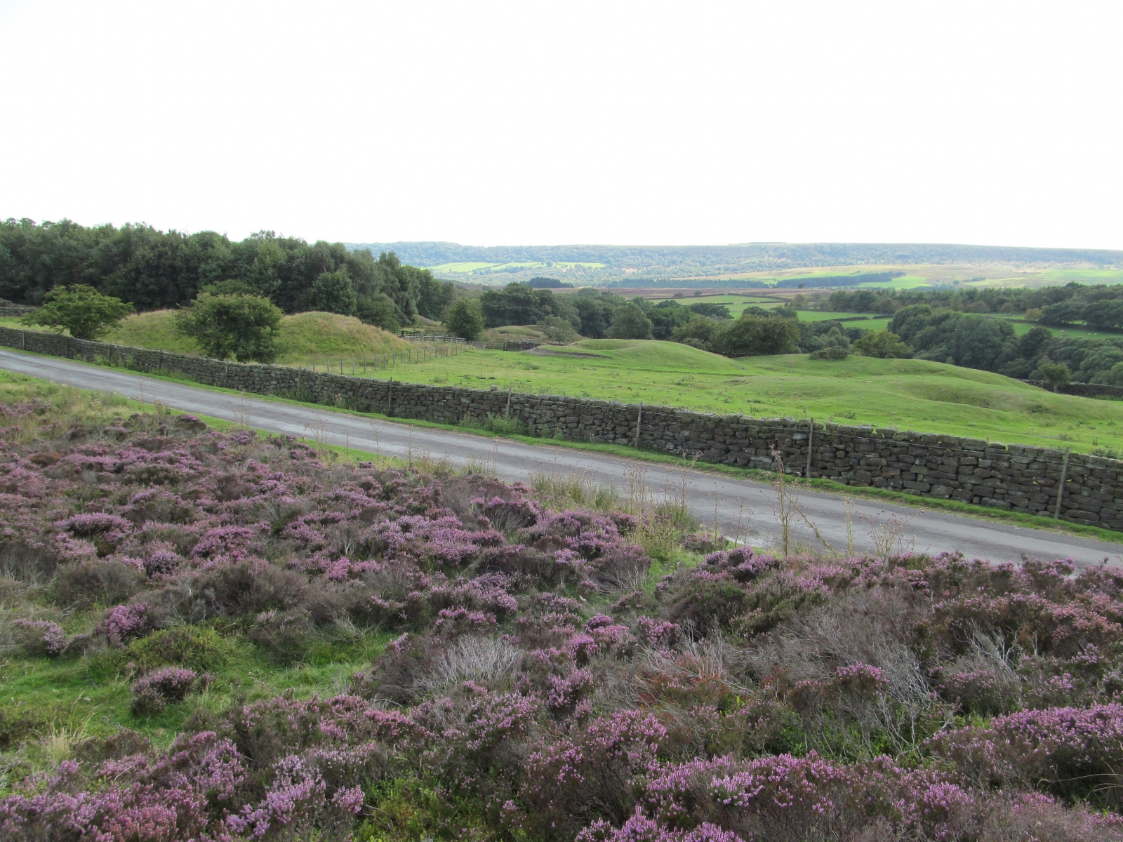


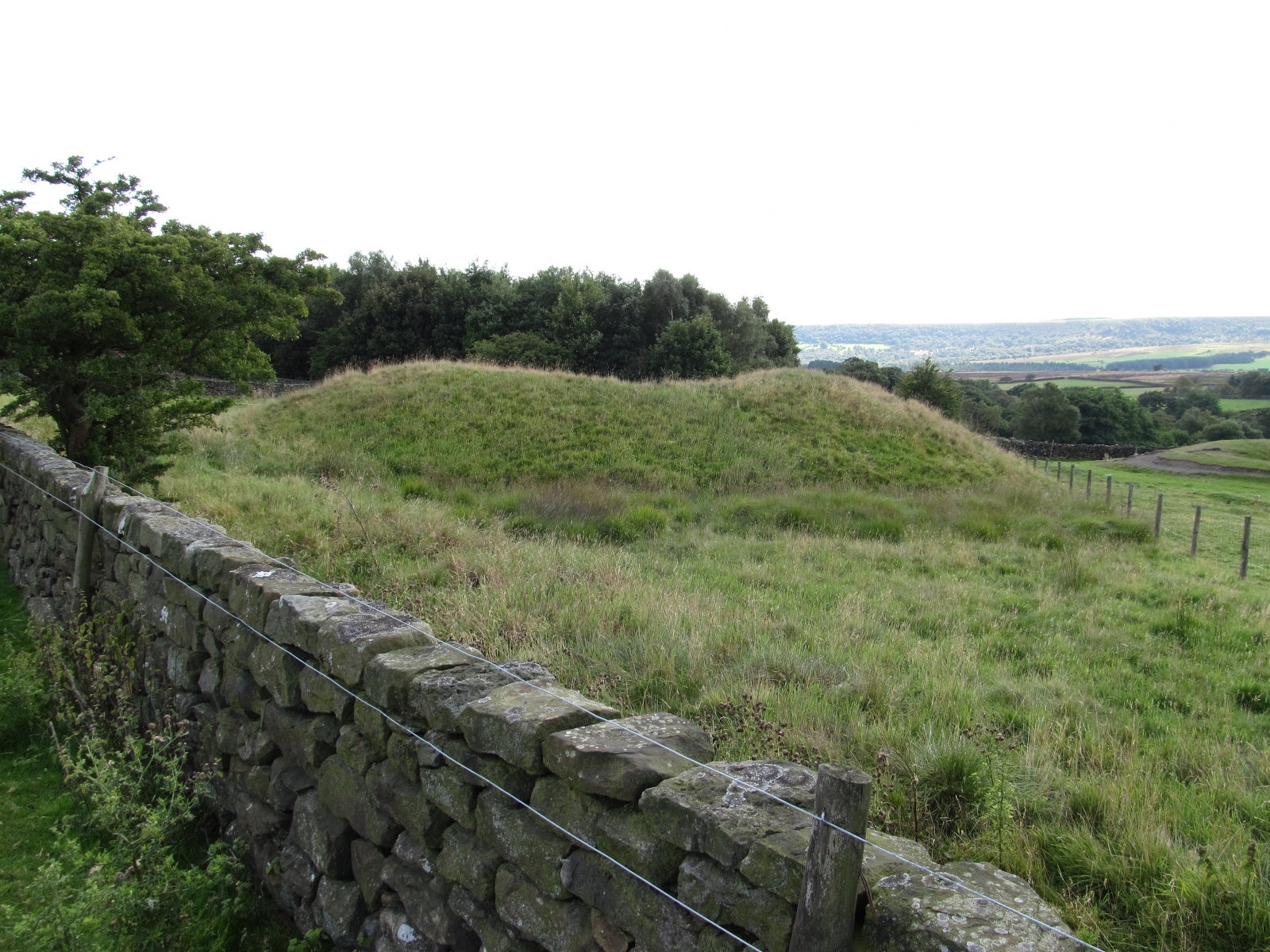
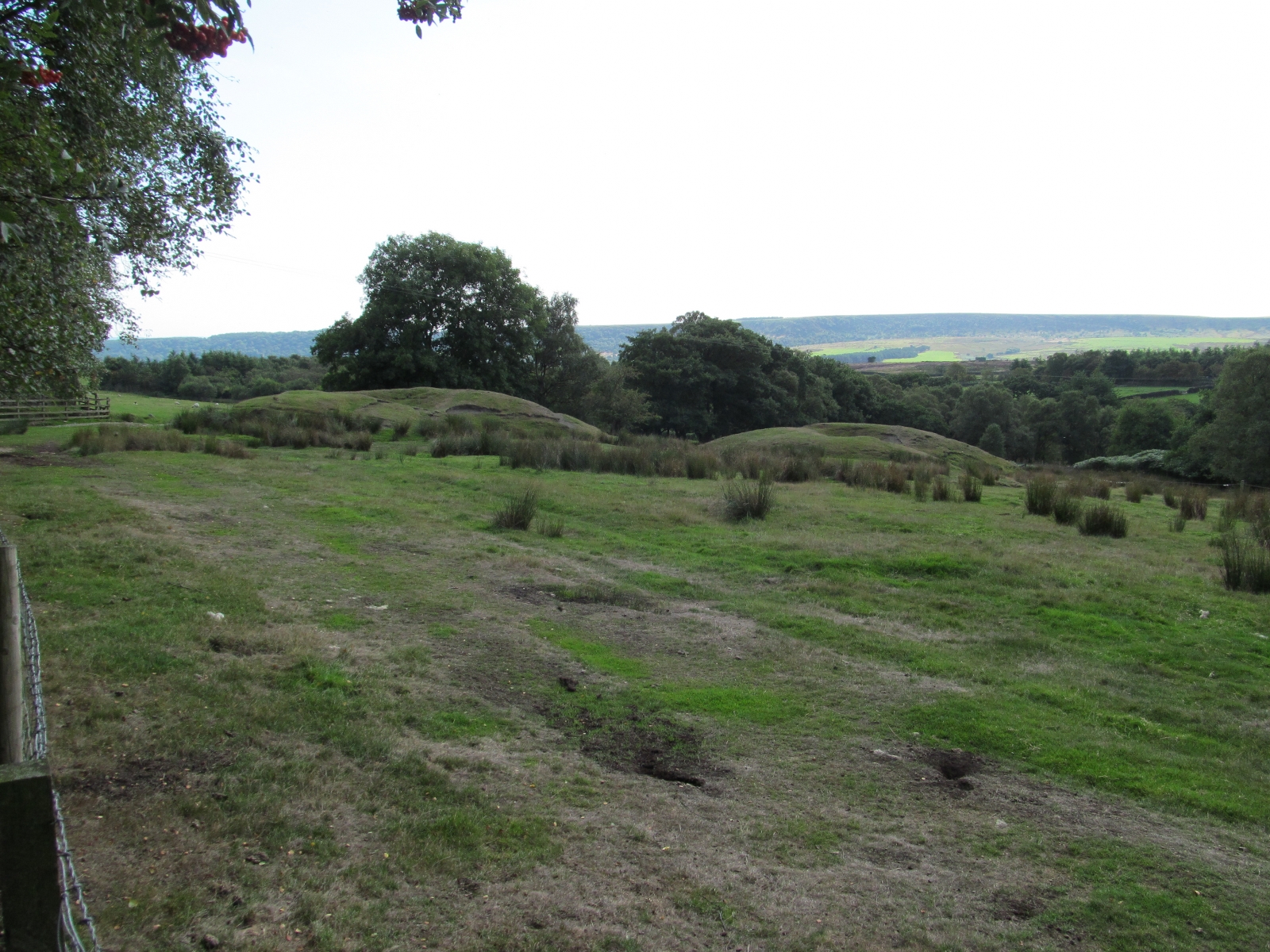
26.08.2013 Rudland Rigg Coal Pits
Reply
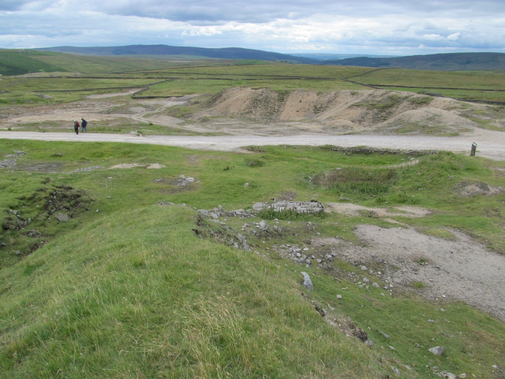
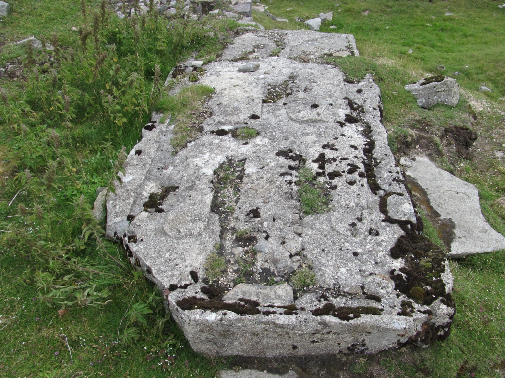
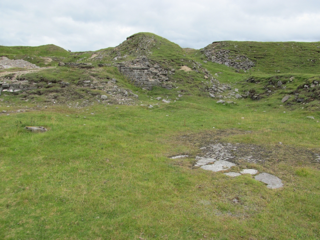
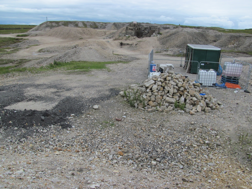
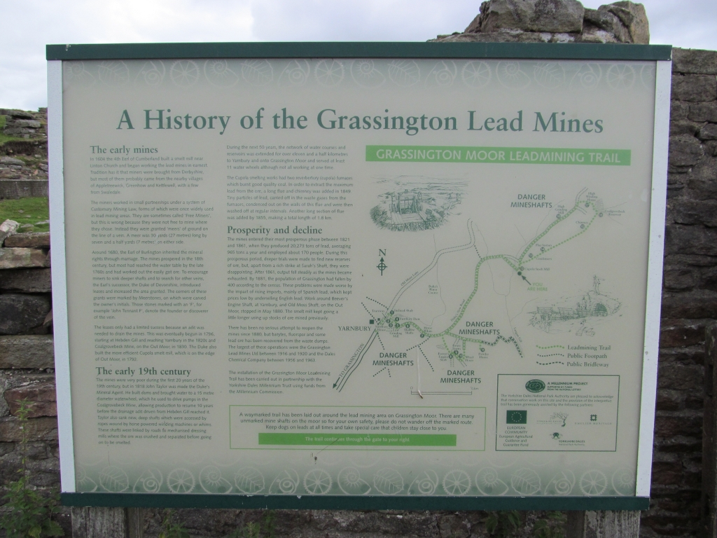
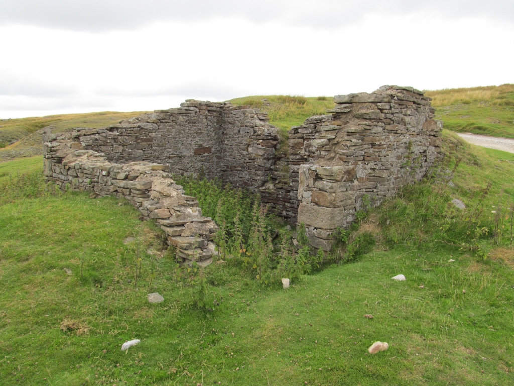
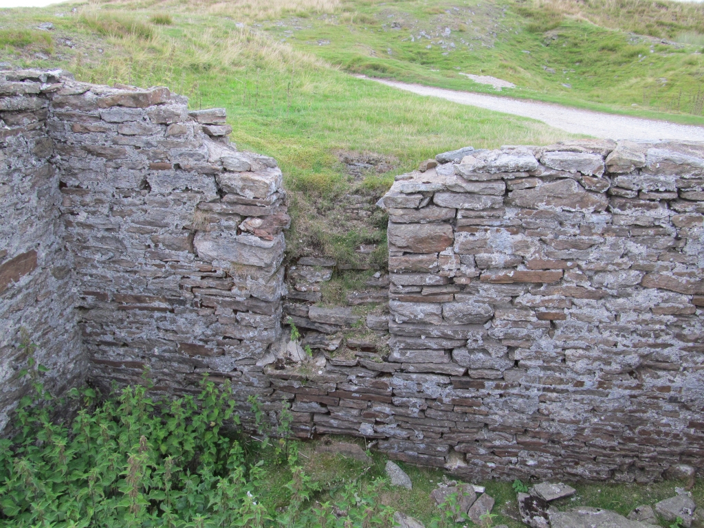
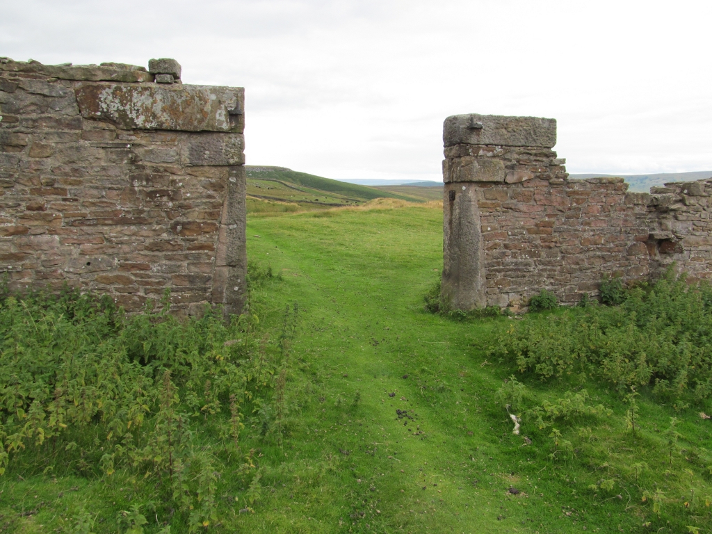
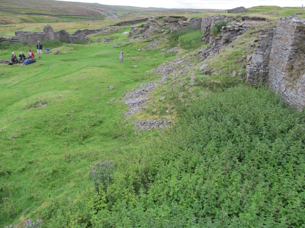
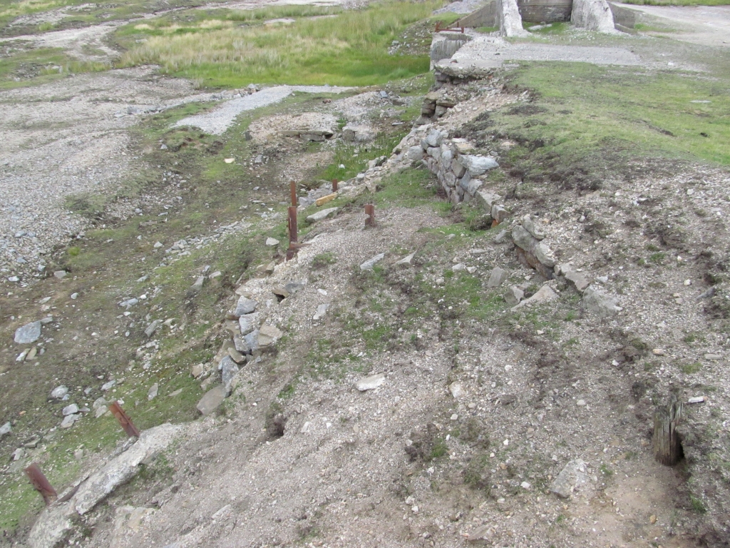
Yarnbury Lead Mine:
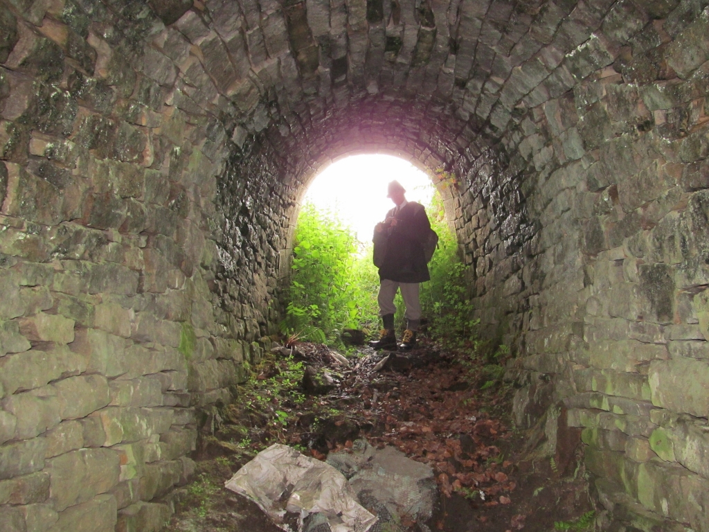
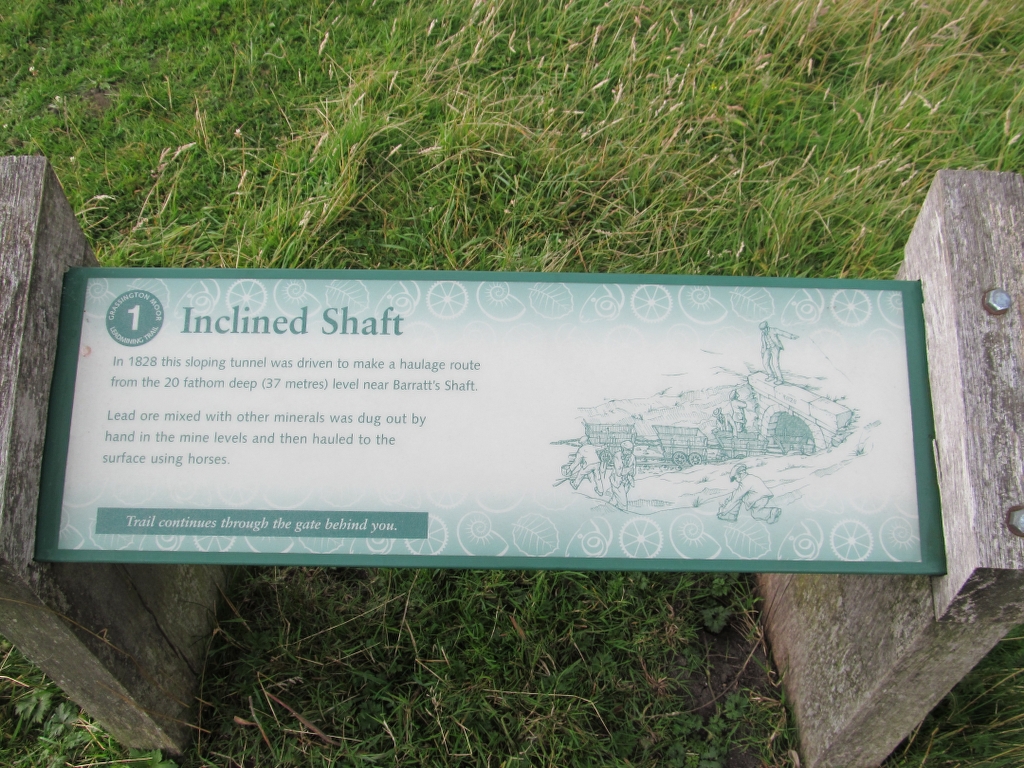
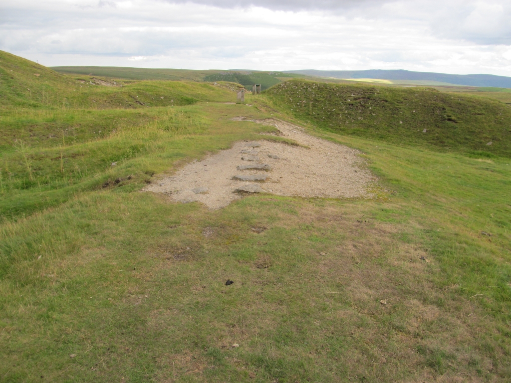
Barratts Incline:

Tramway From Barratts Shaft + Low Grinding Mill:


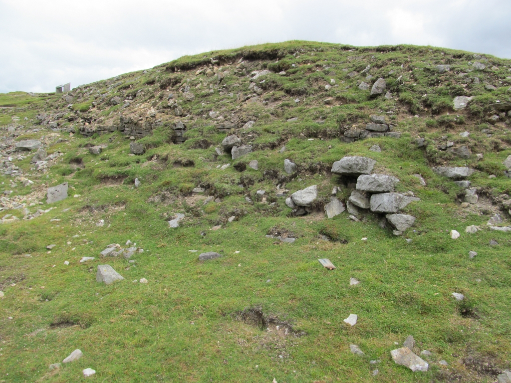

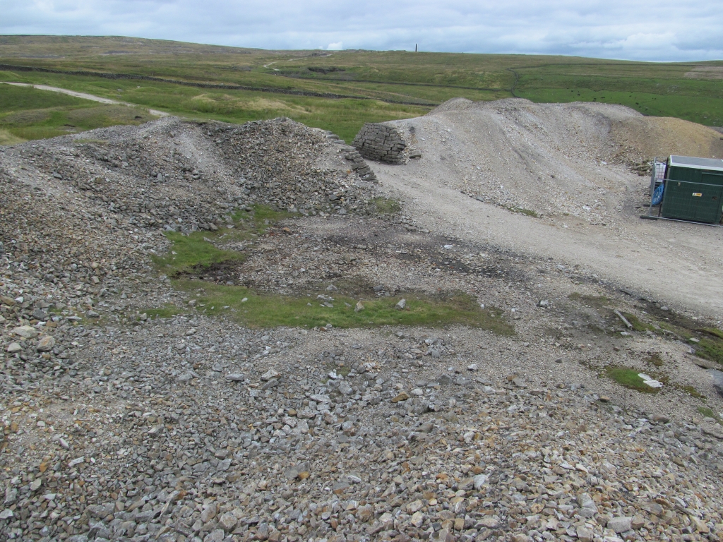
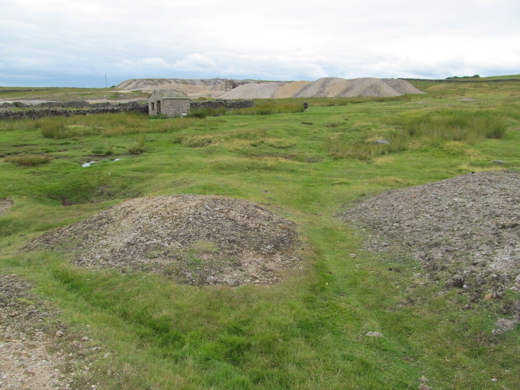
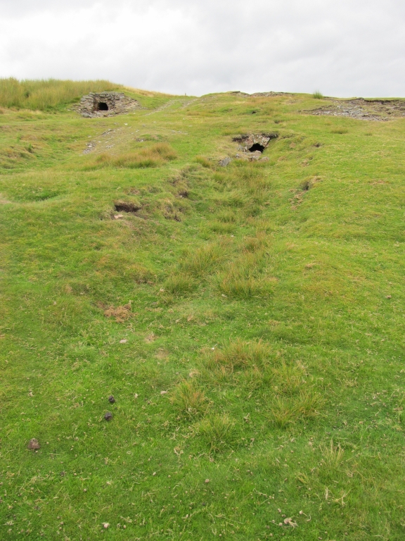
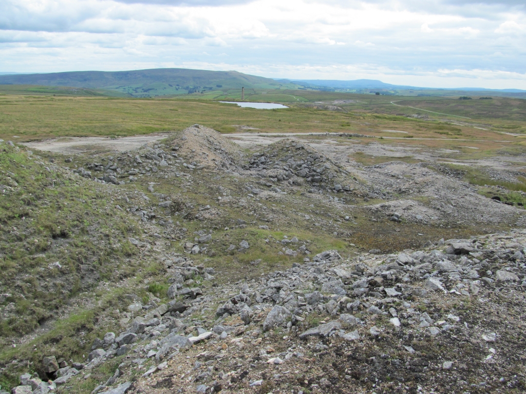
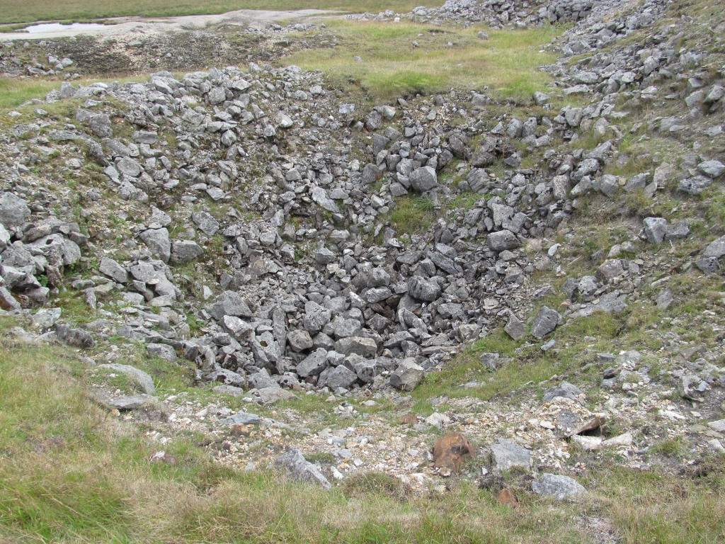
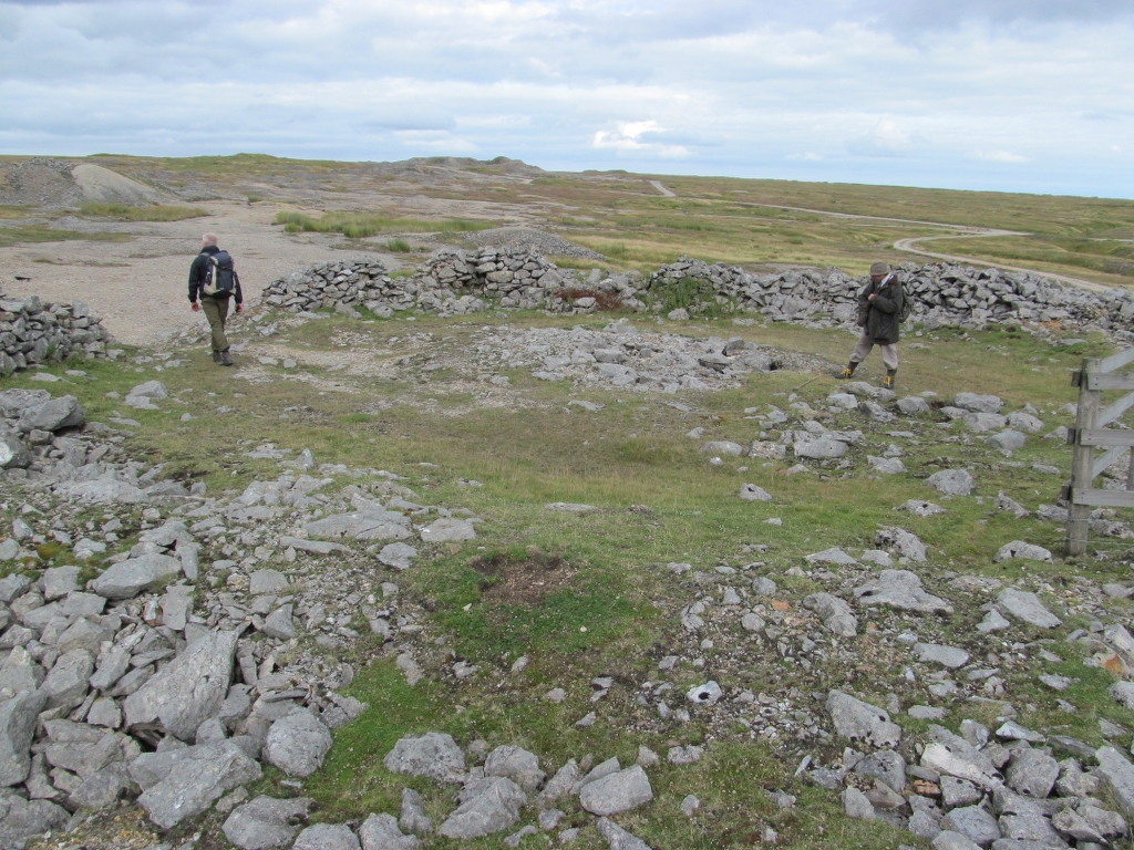
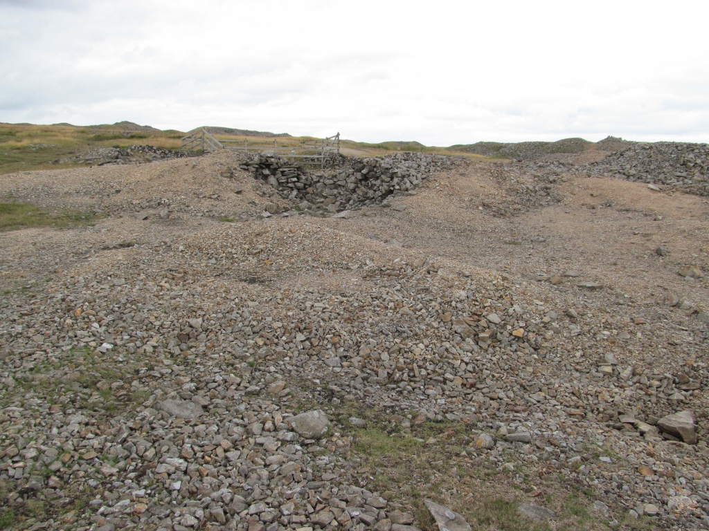
Nearby Old Shafts:

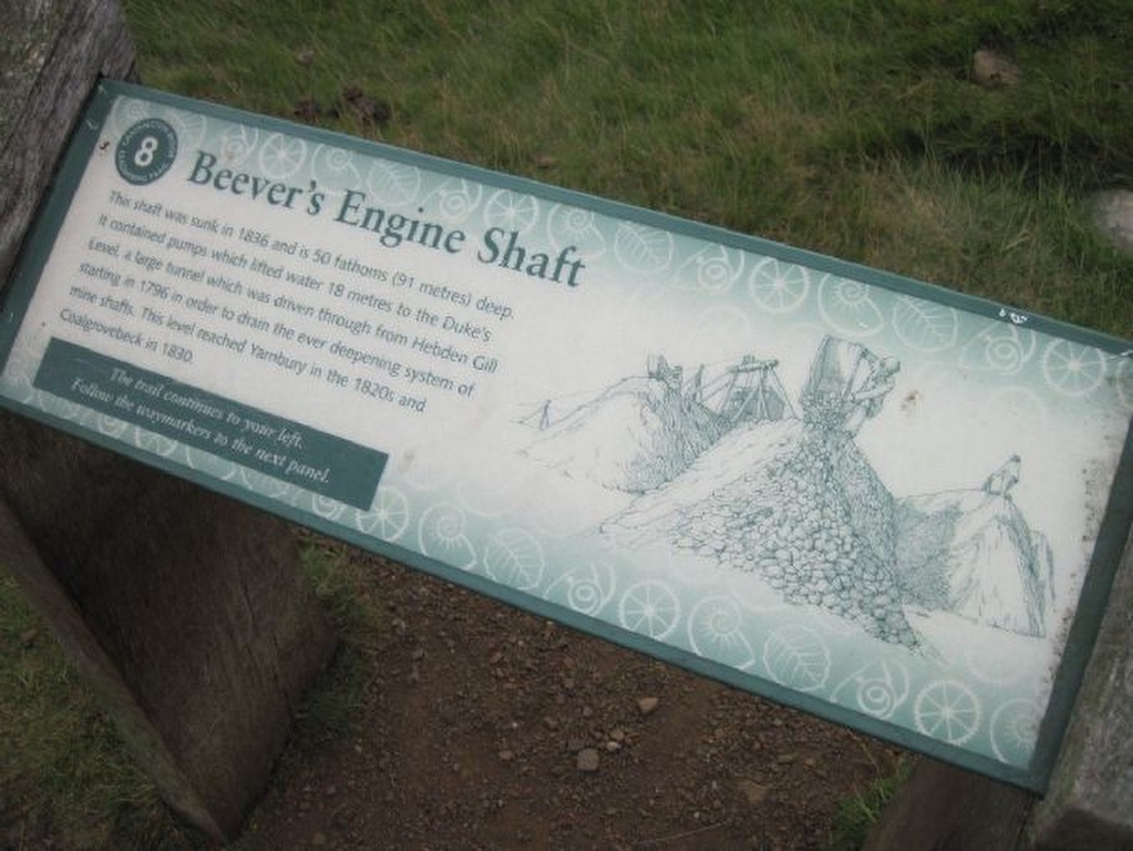
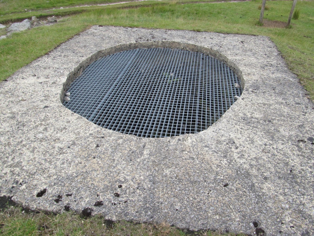
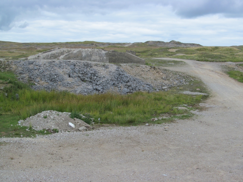
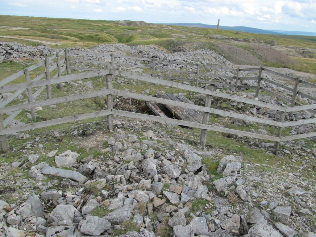
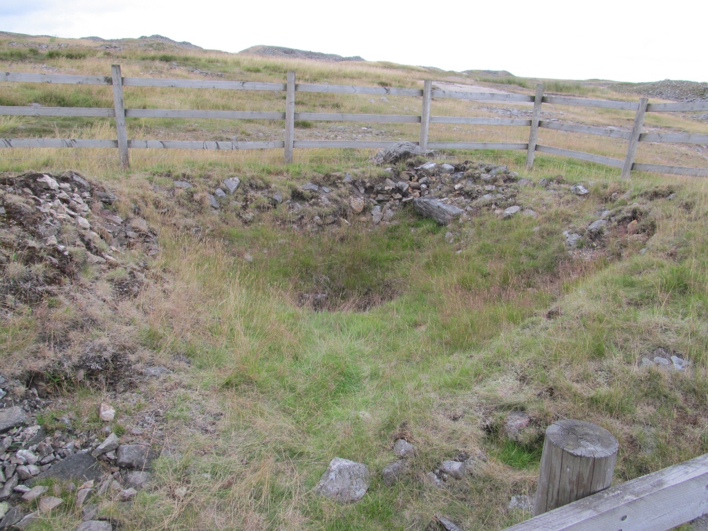
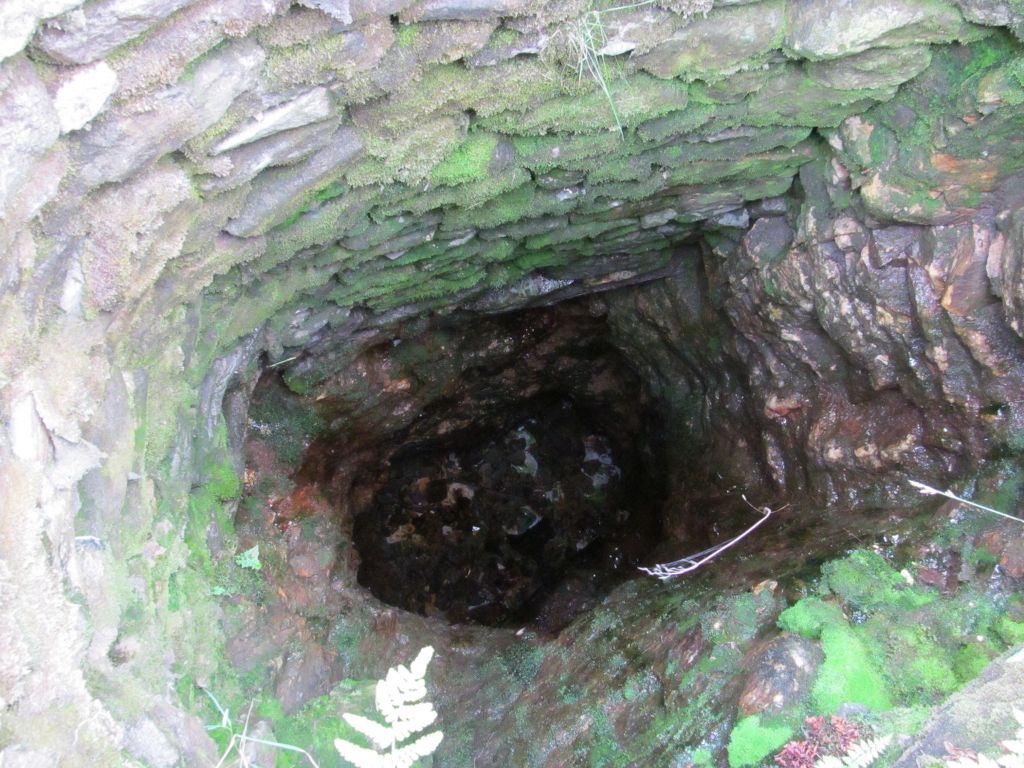
Beever’s Shaft:
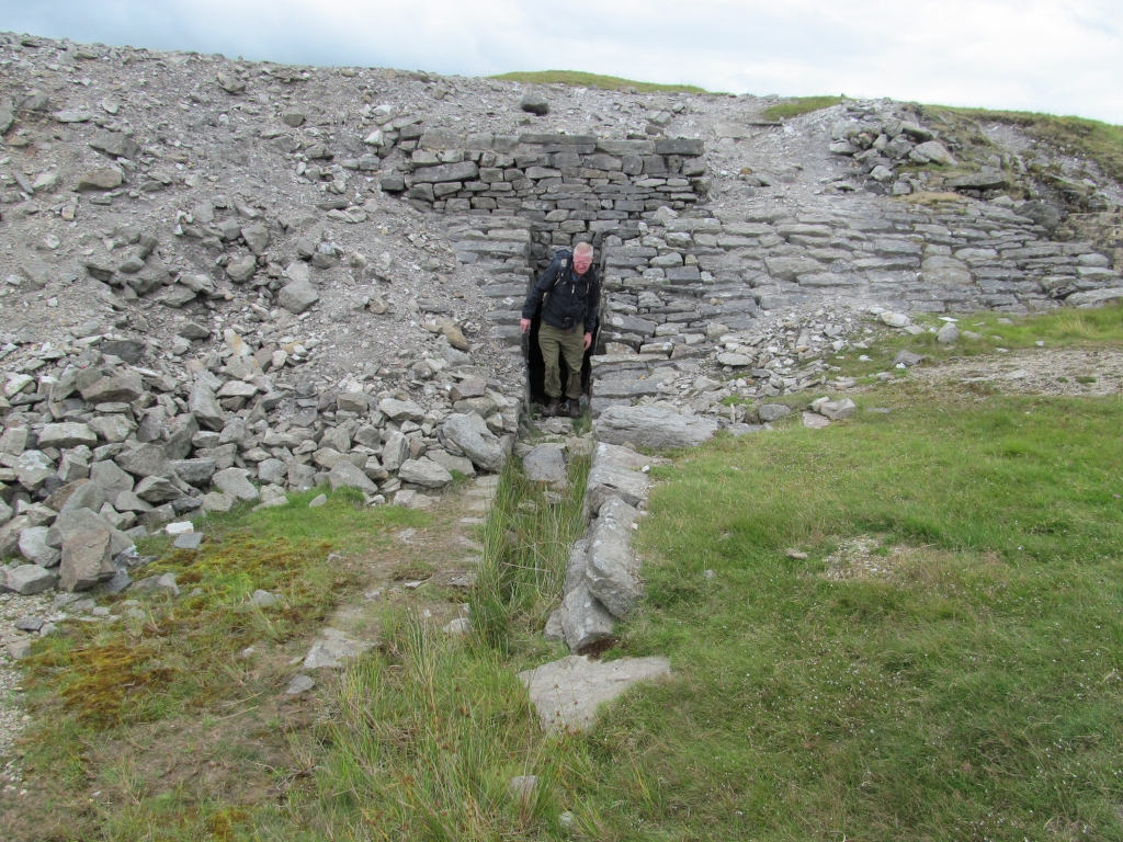
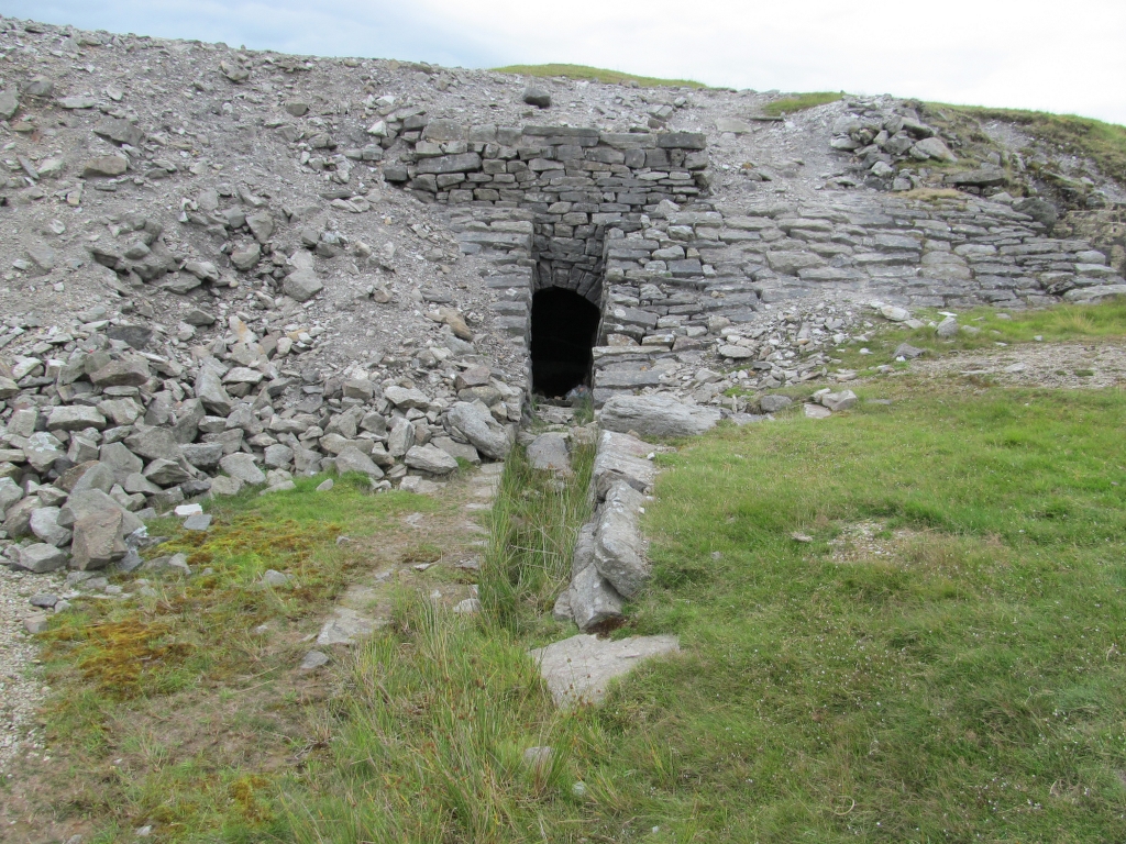
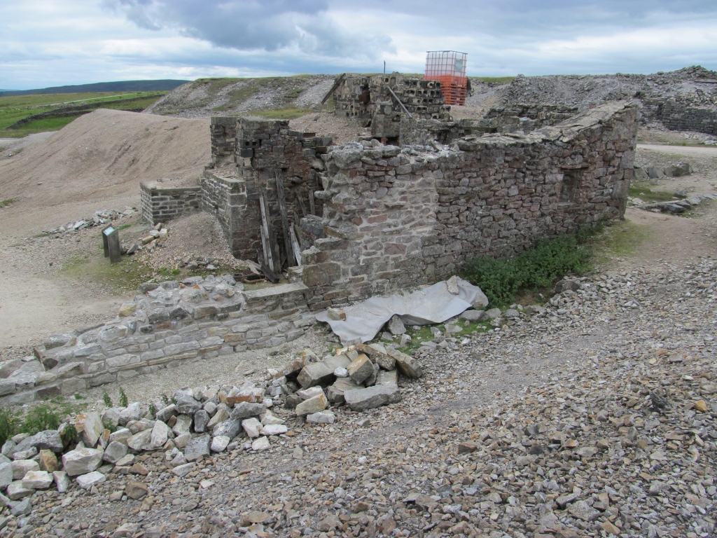
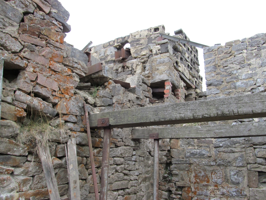
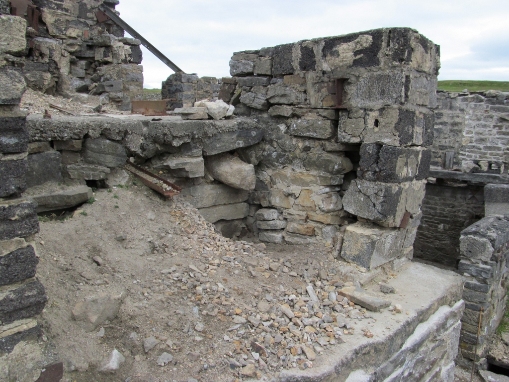
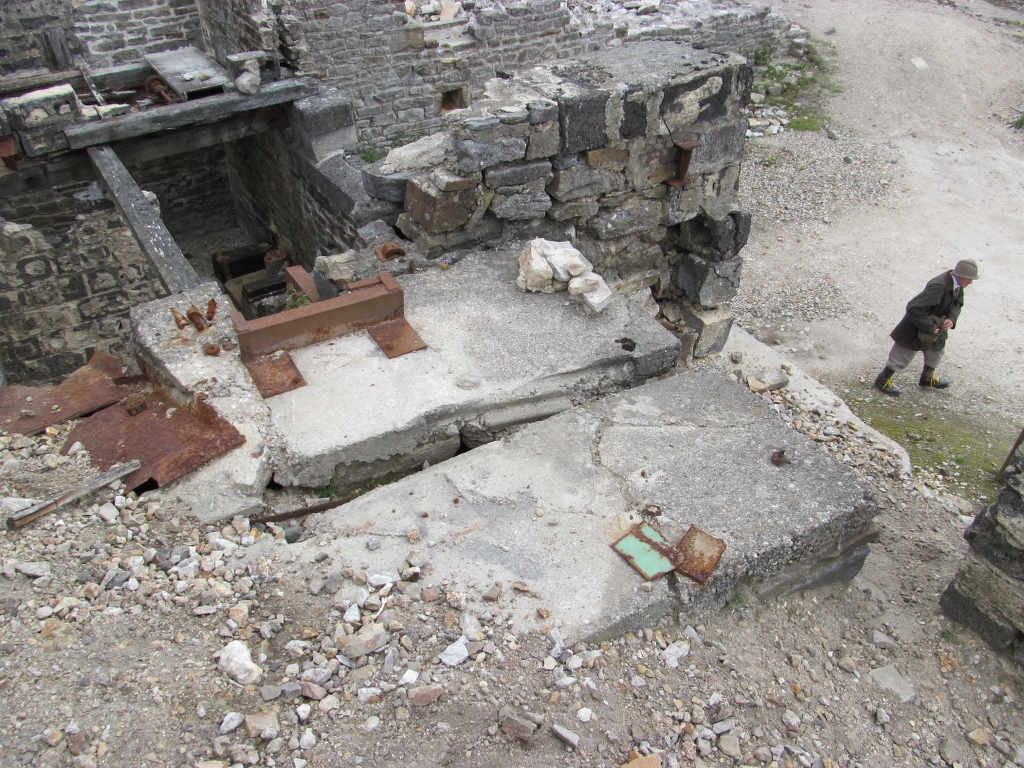
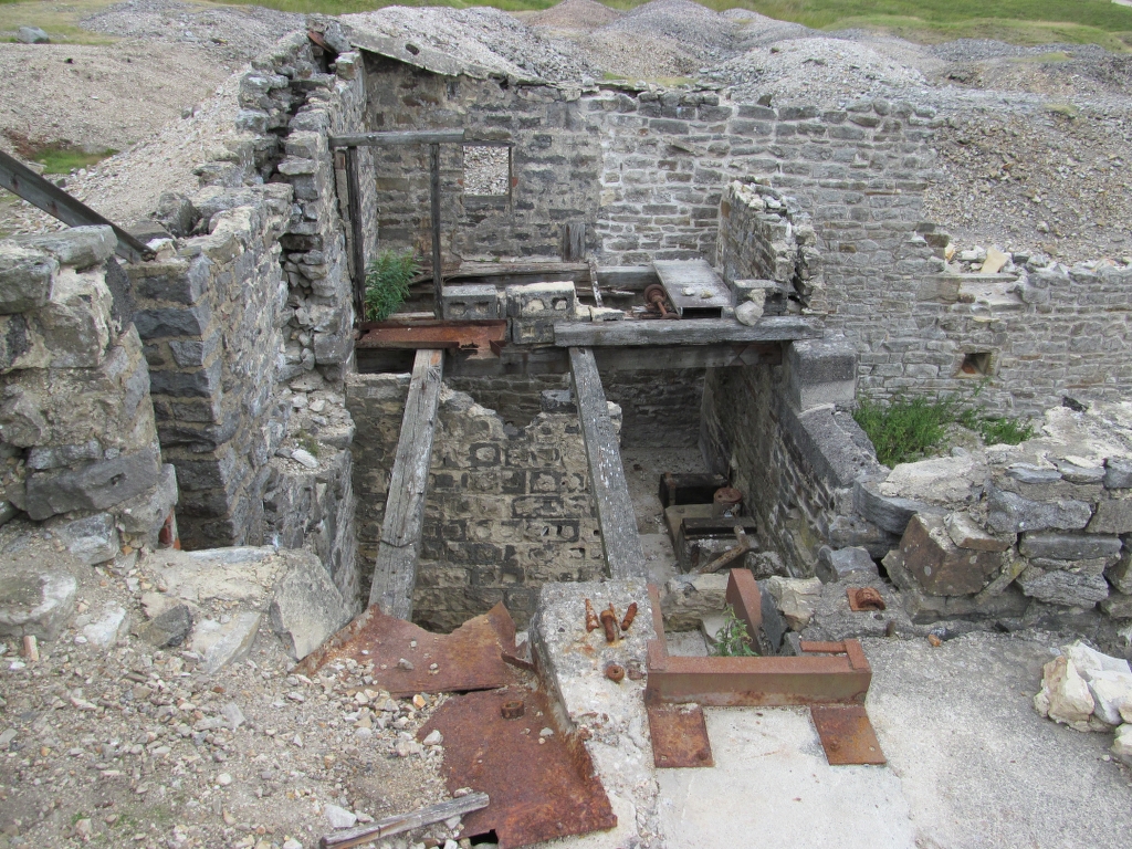
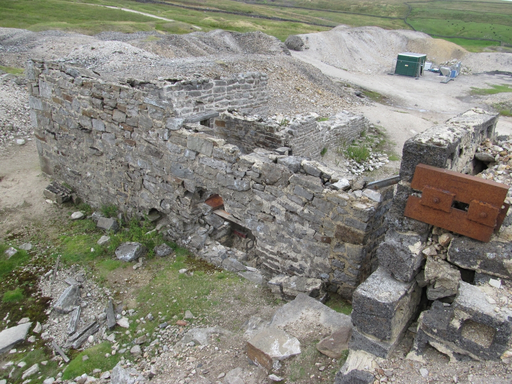
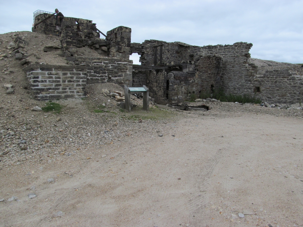
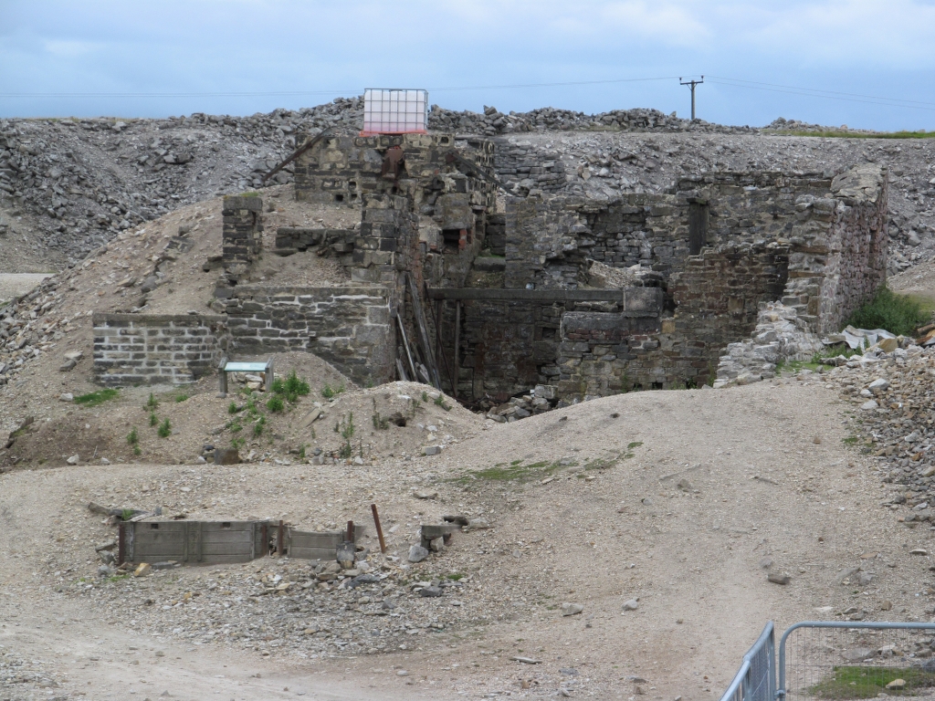
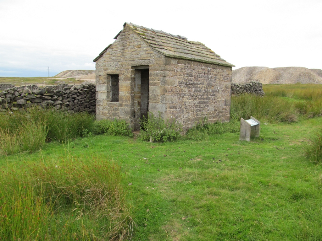
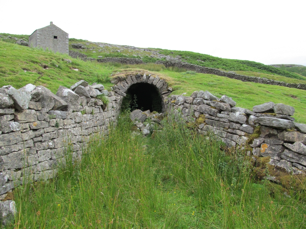
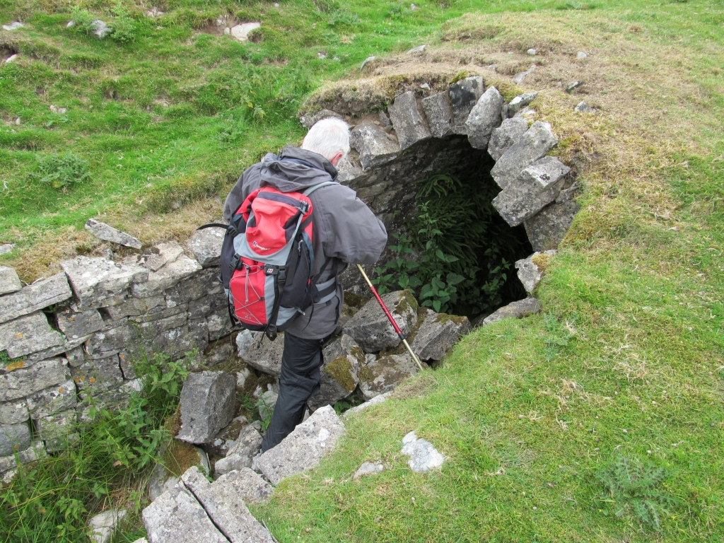
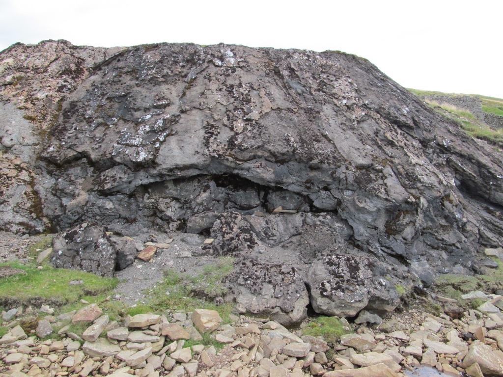
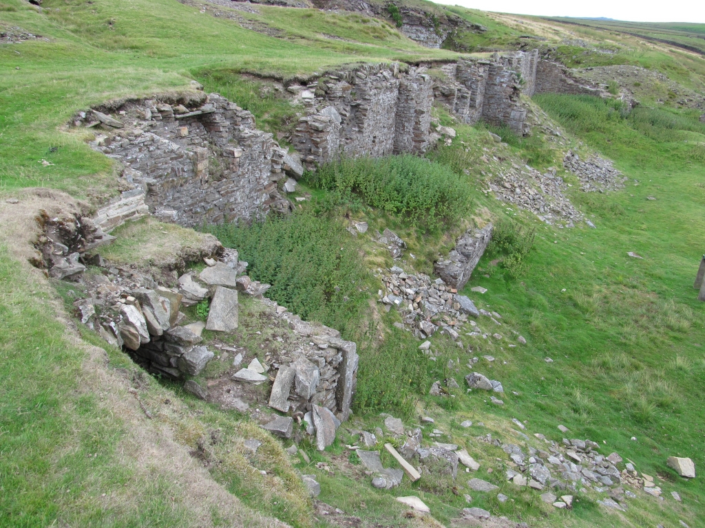
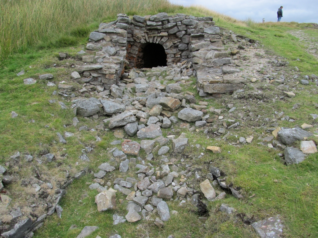
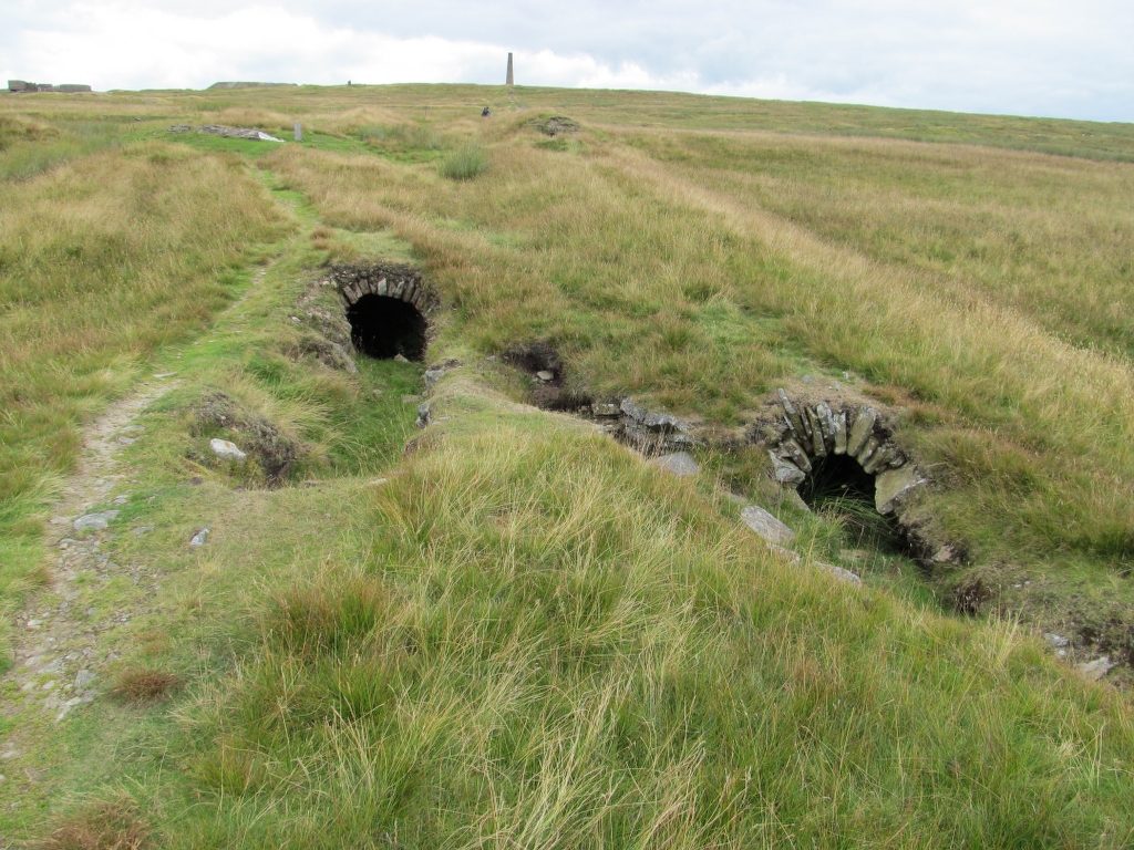
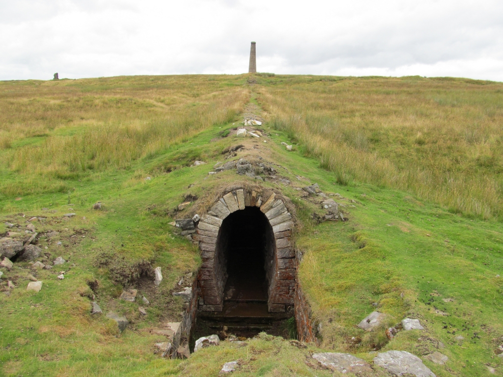
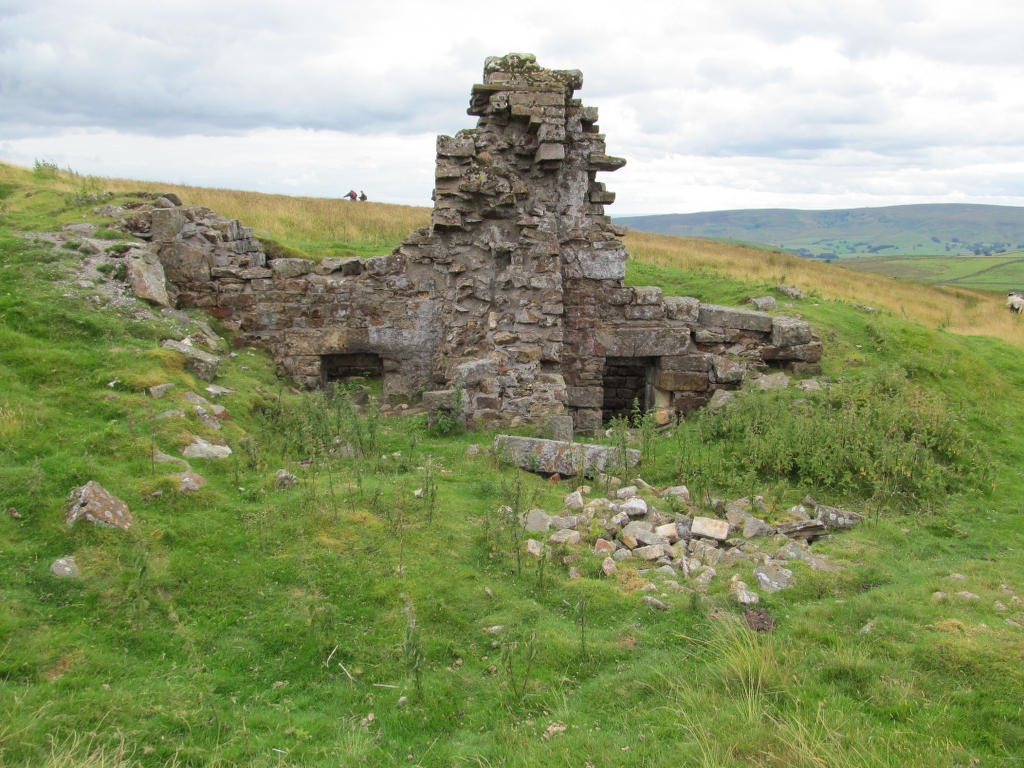
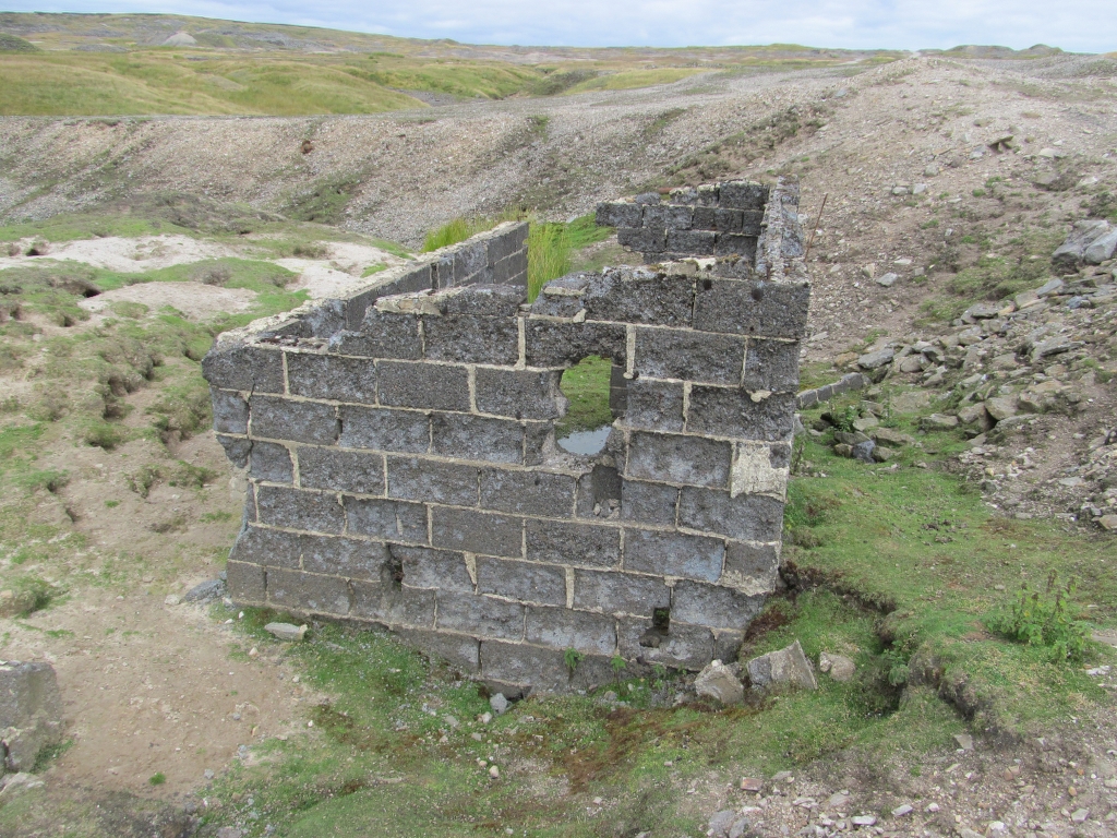
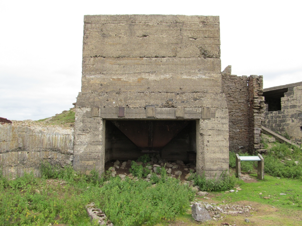
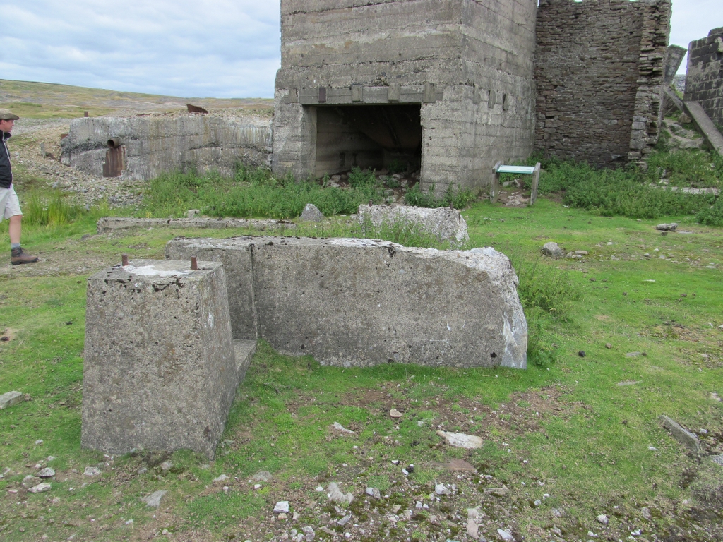
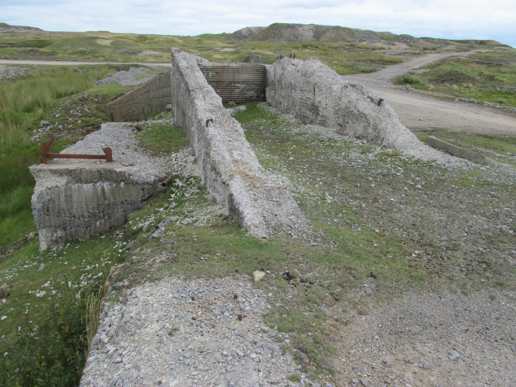
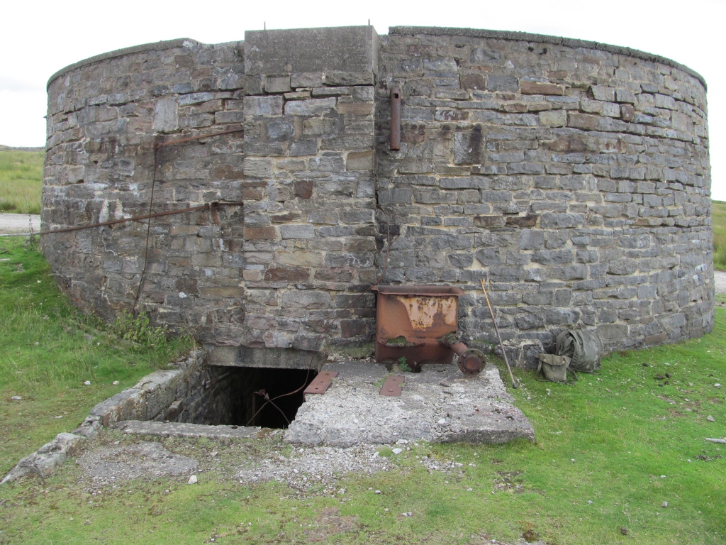
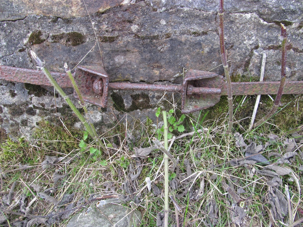
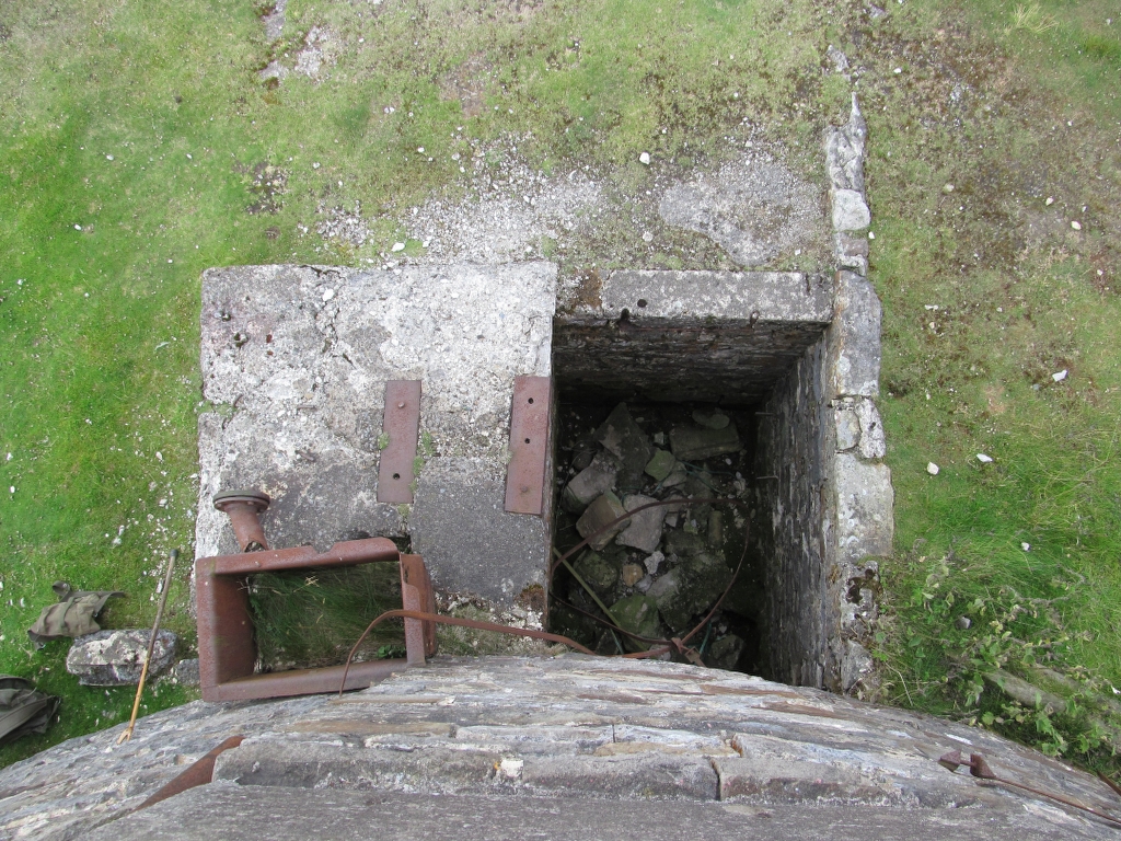
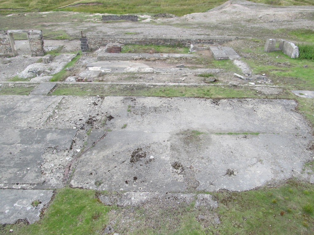
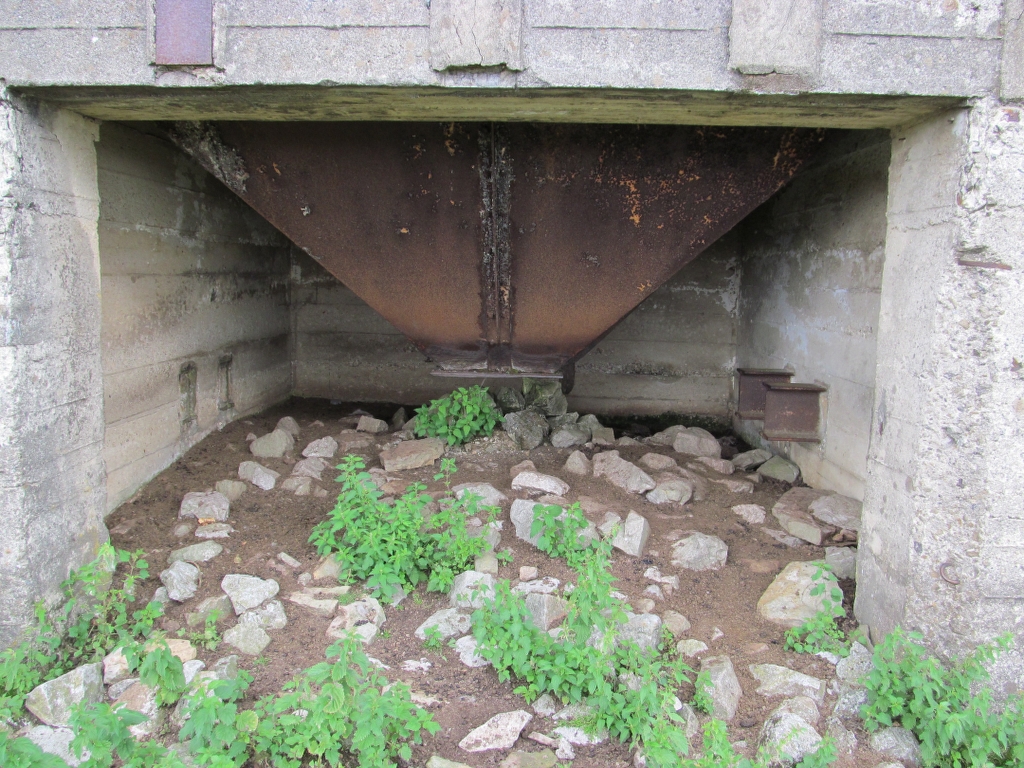
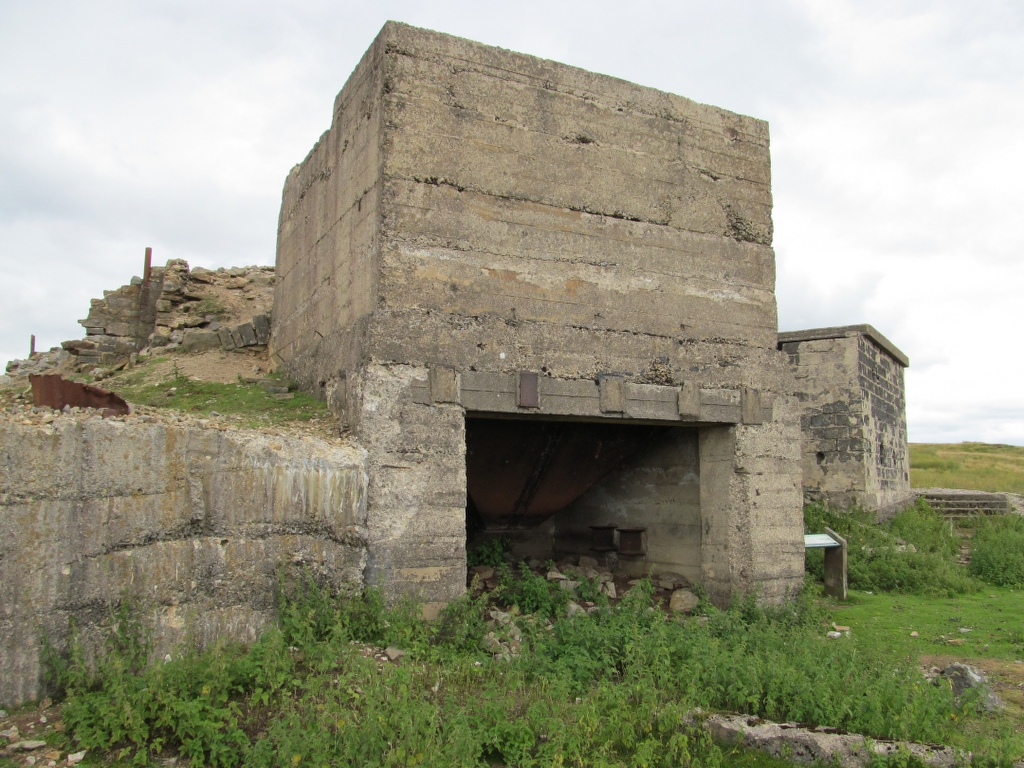
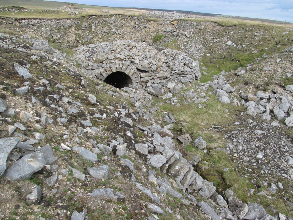
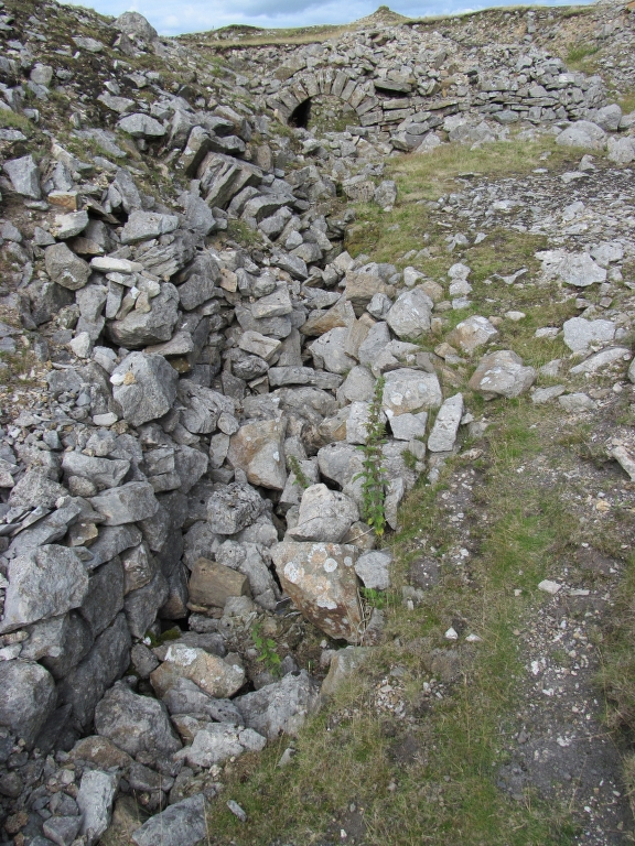
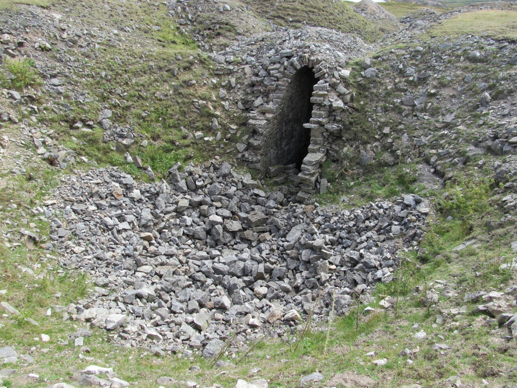
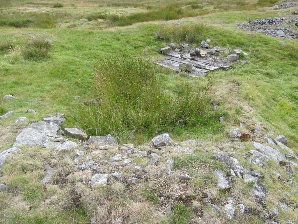
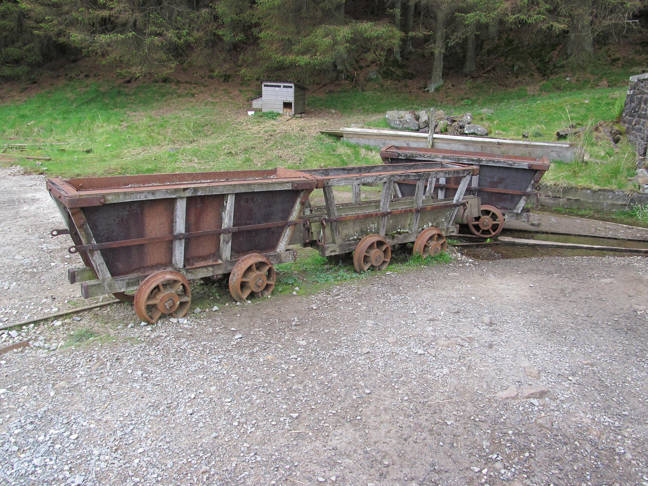
Engine Shaft, Pump Rod Chamber + Bouse Teams:


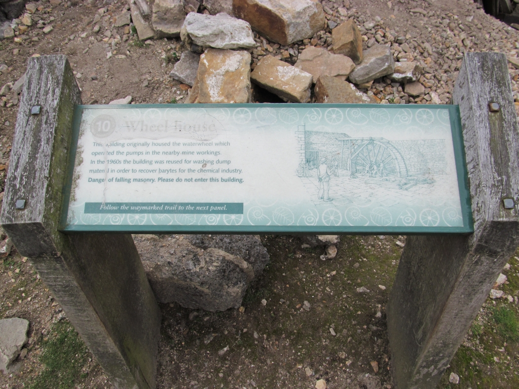
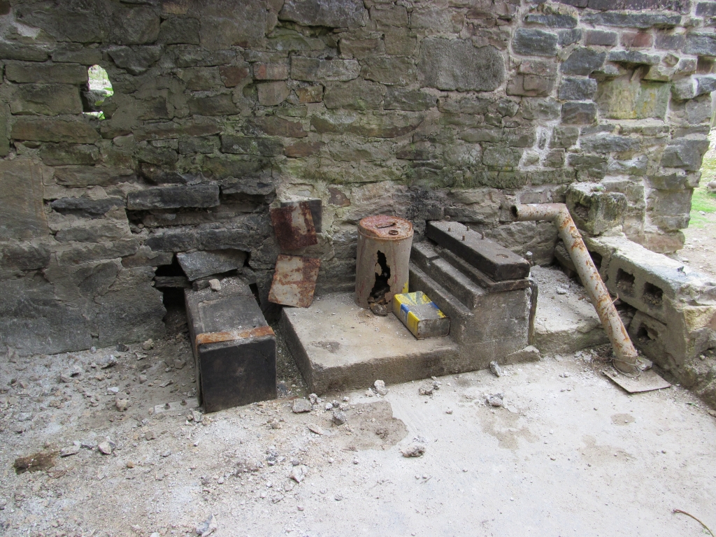
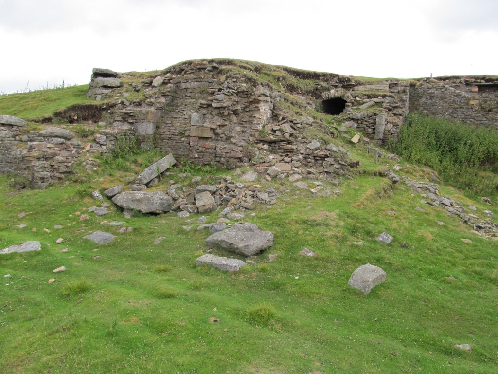
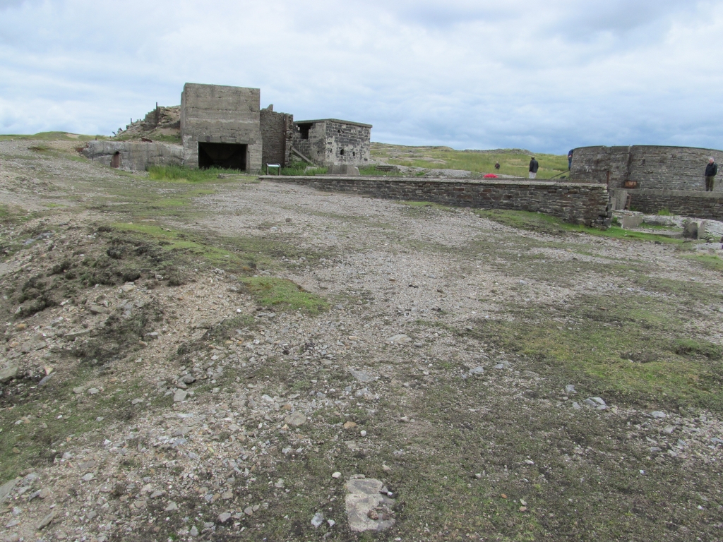
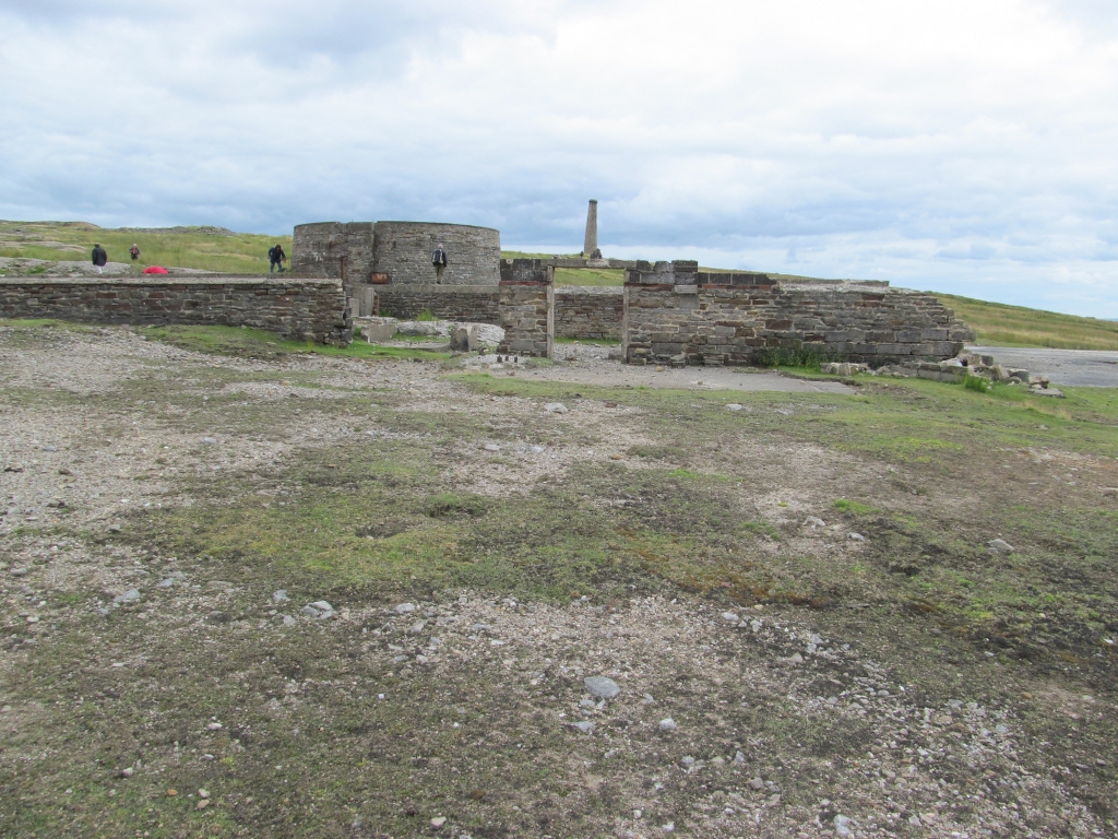
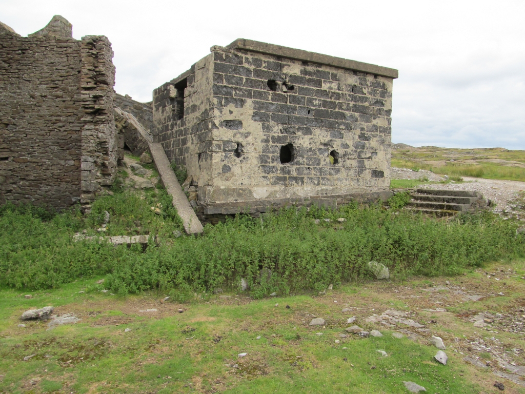
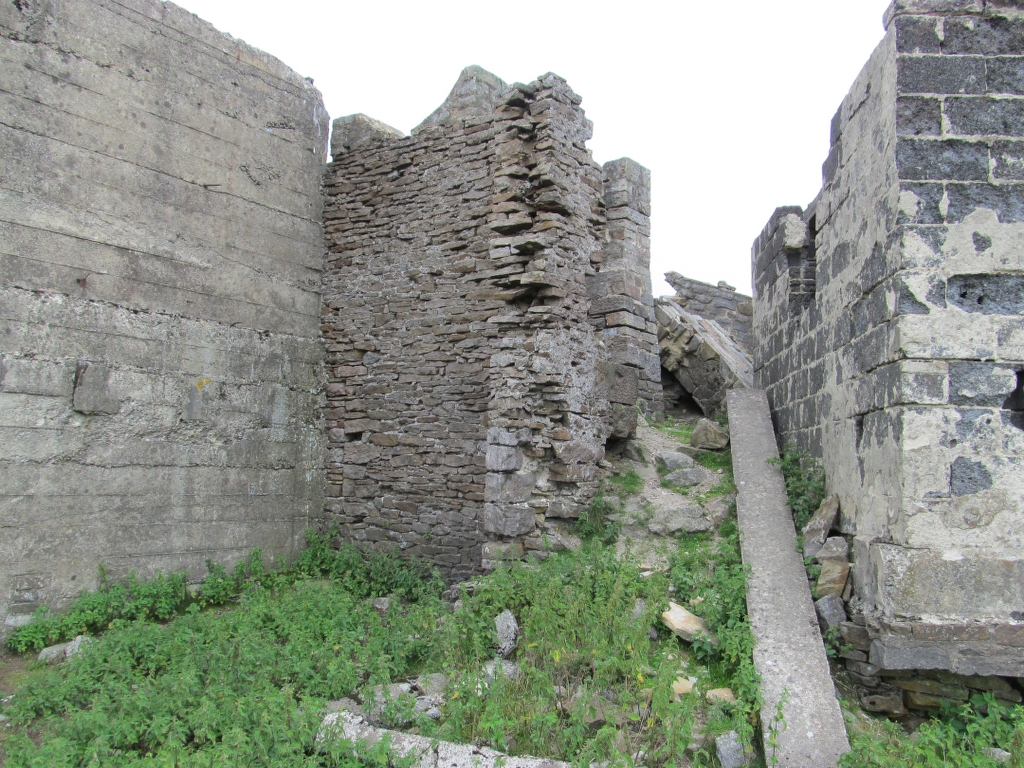
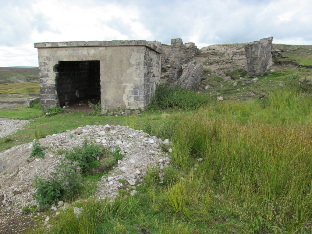
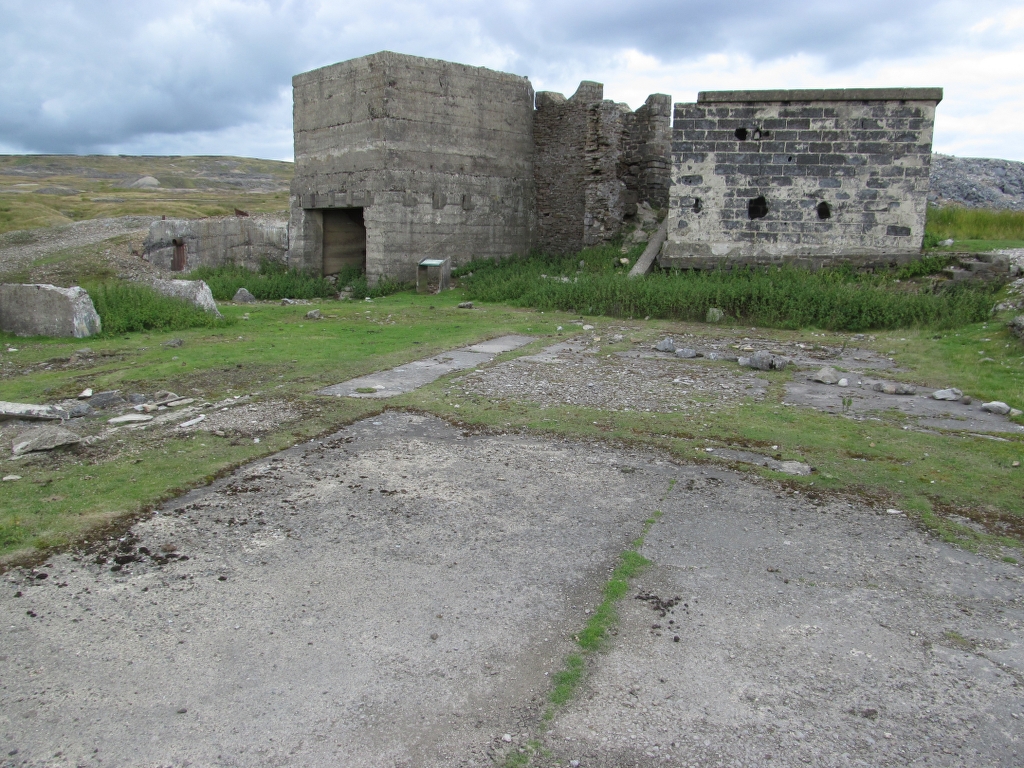
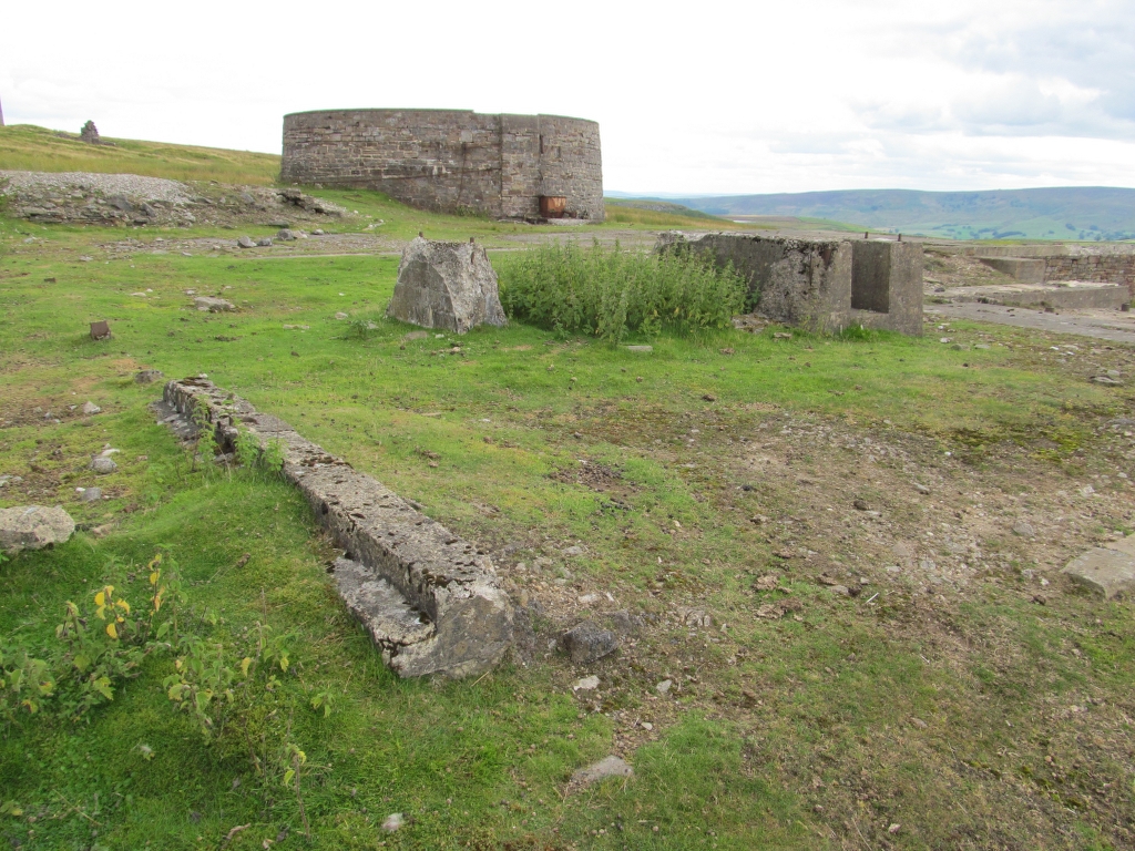
Wheelhouse, Crinding Mill + Byrates Processing Mill:


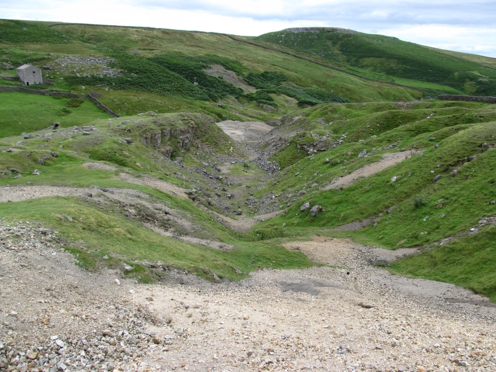
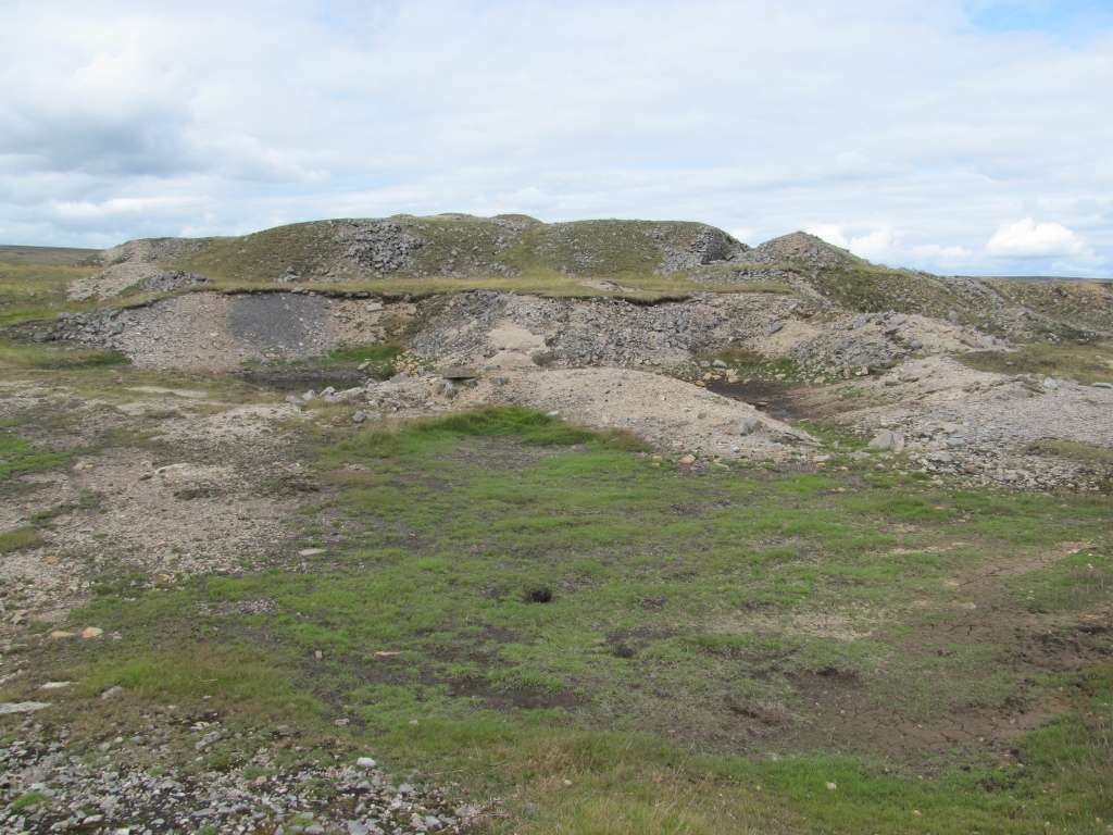
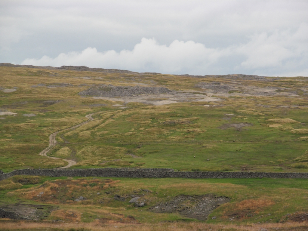
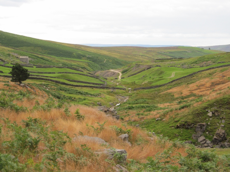
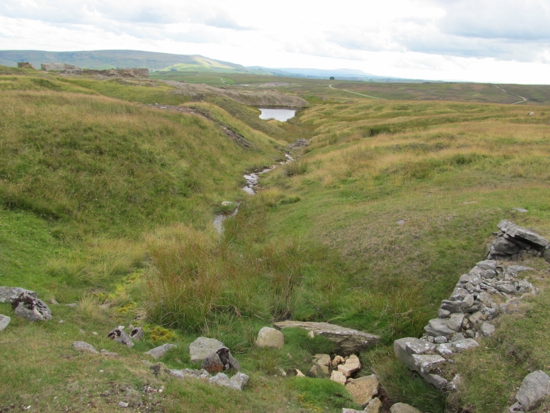
Cockbur Lead Workings:
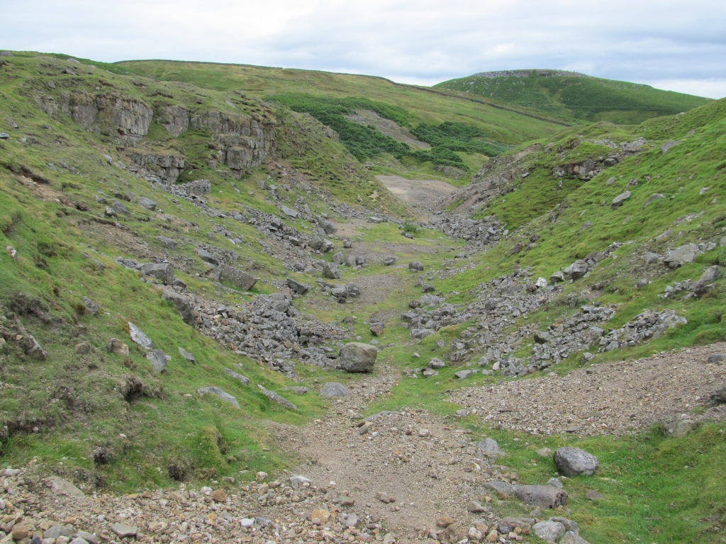
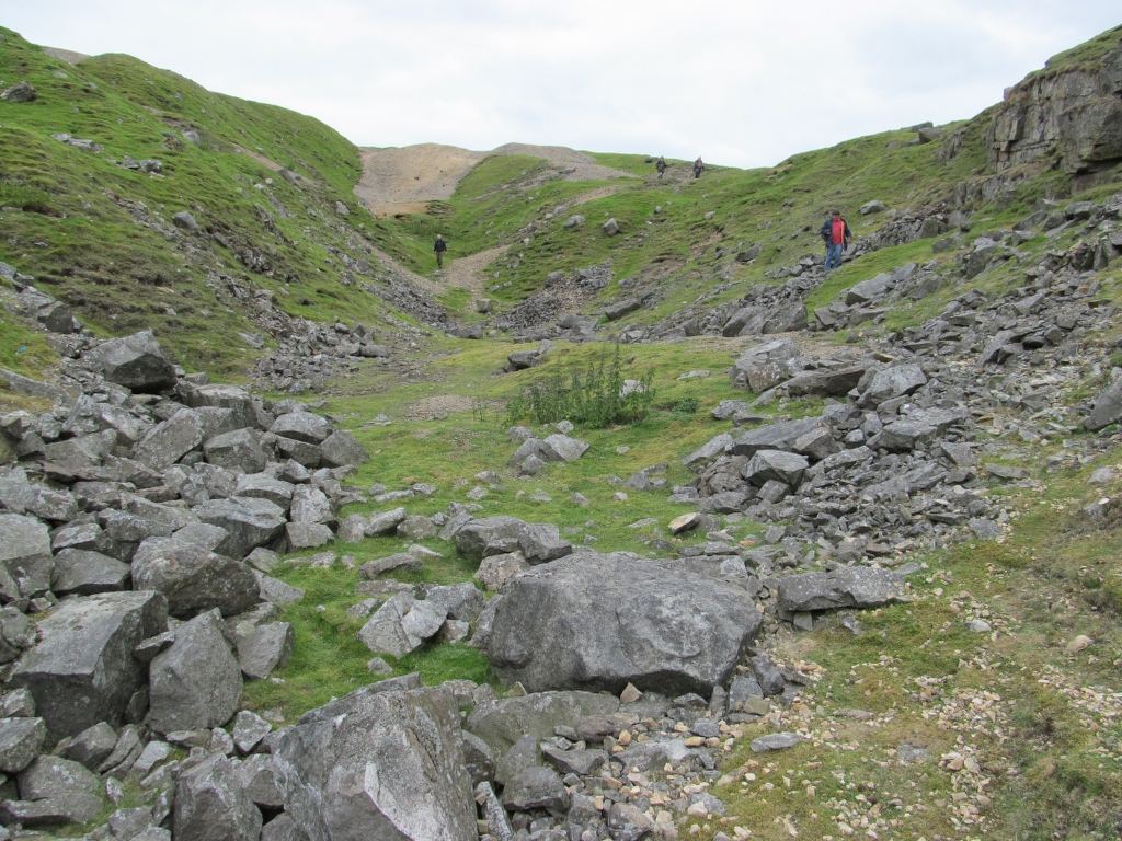
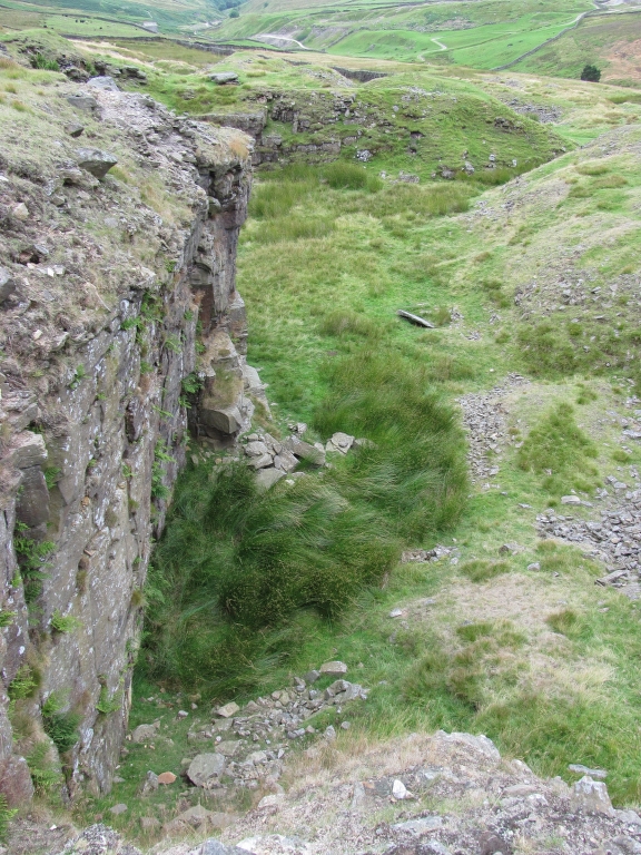
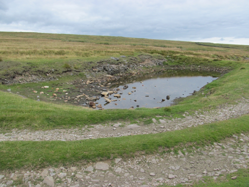
Cockbur Hush:


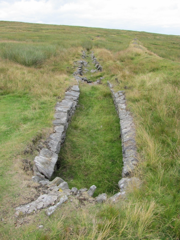
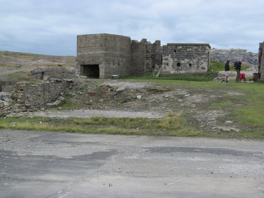
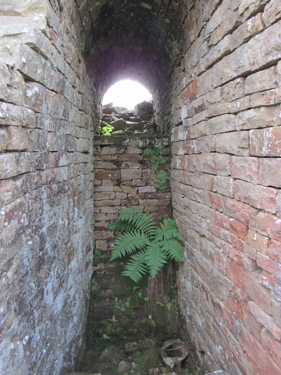
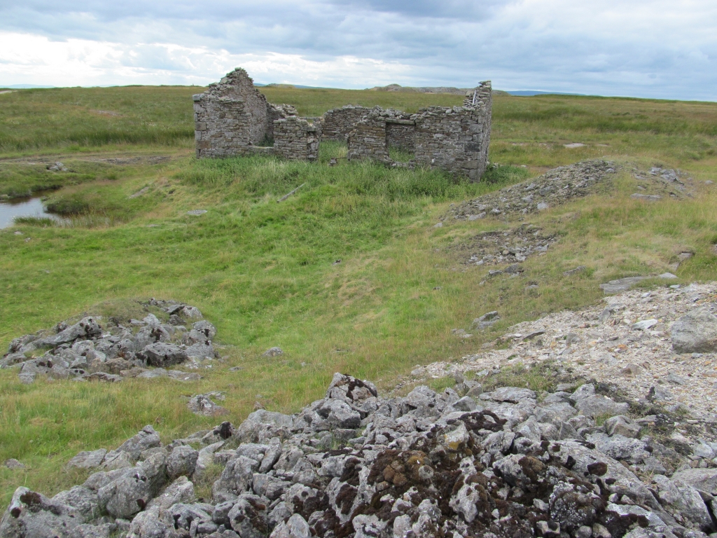
The Powder Magazine:


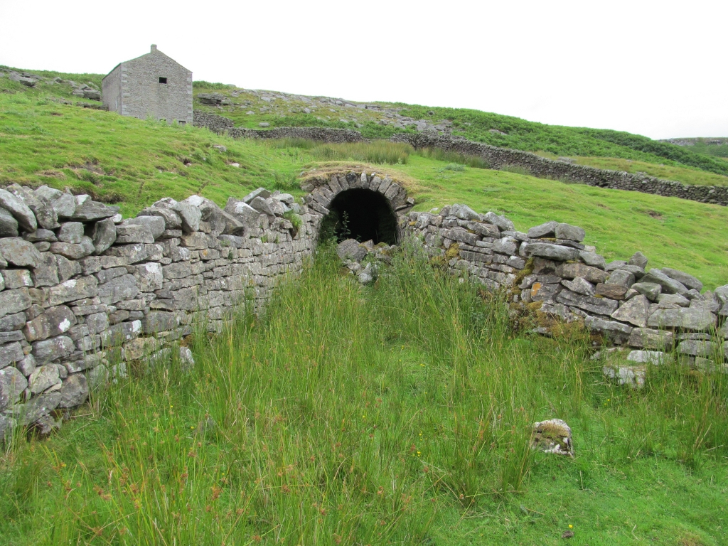
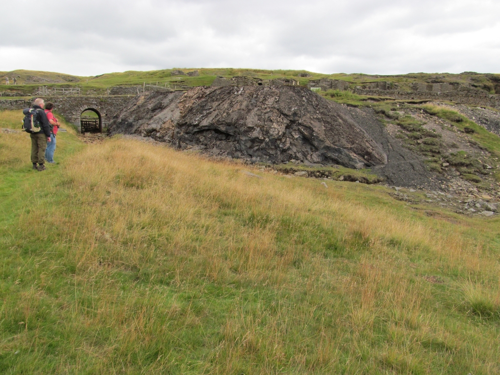
Blue Level:

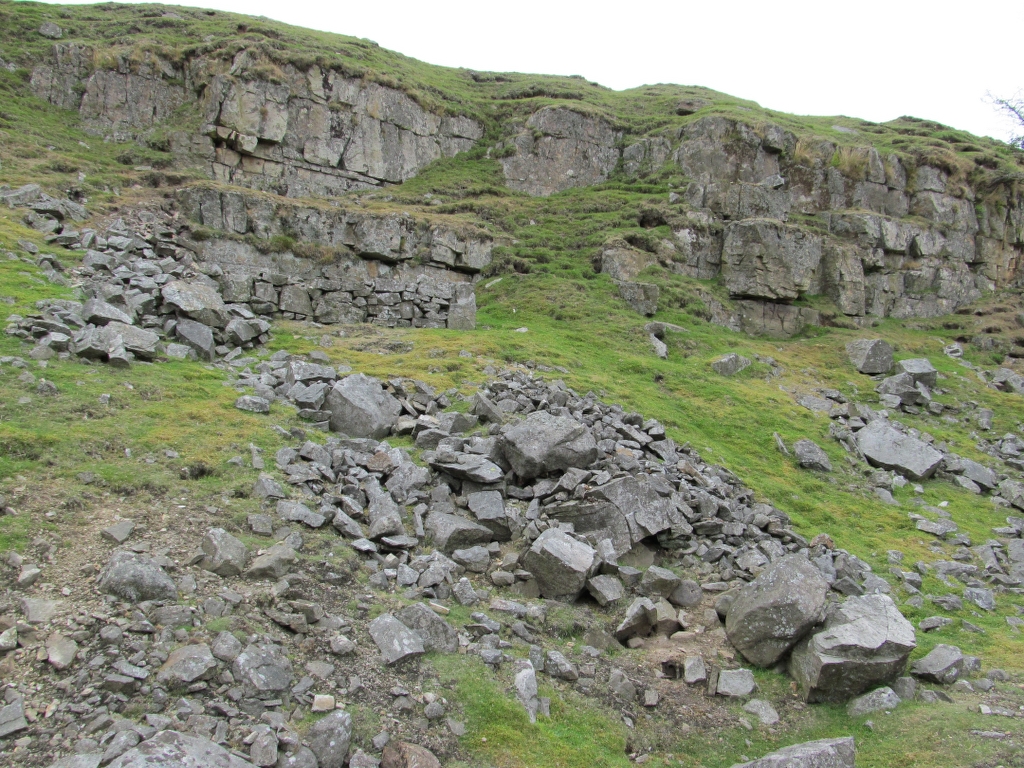
Limestone Quarry Near Cupola Smelt Mill:


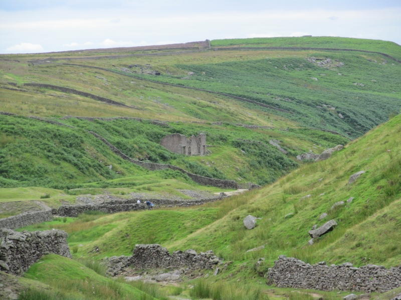
Cupola Smelt Mill:


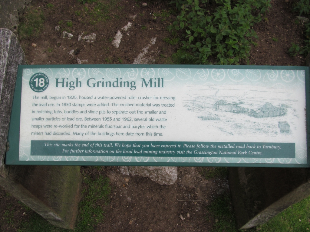
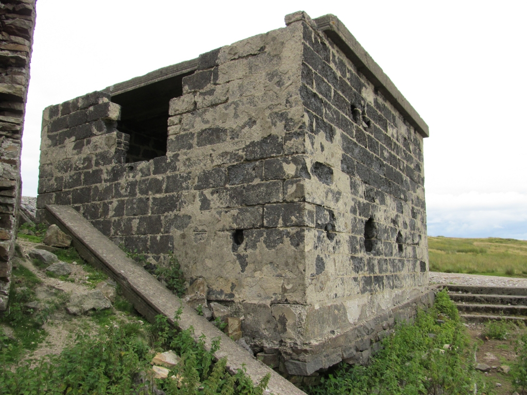
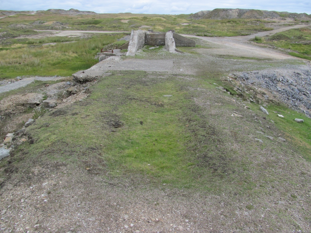
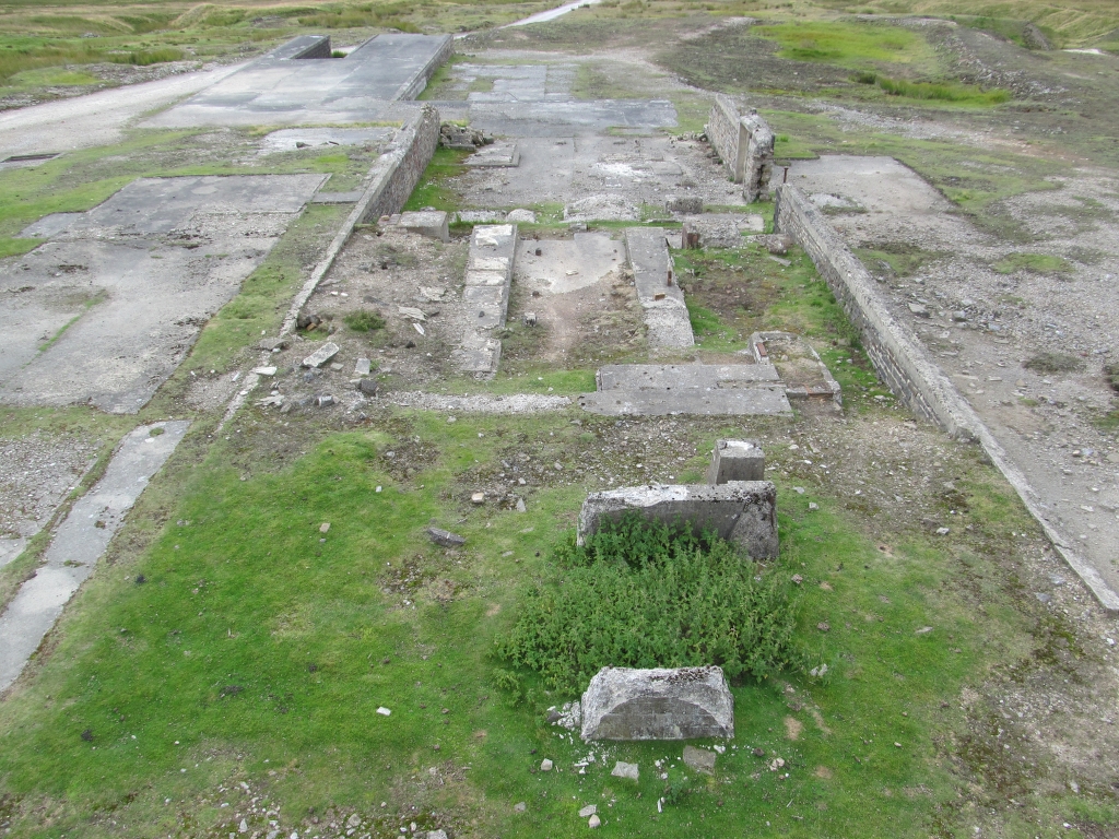
High Grinding Mill:


Coalgrovehead Mine:
Old Moss Shaft:


Sarah’s Shaft:


Low Peru Shaft:


Taylors Shaft:


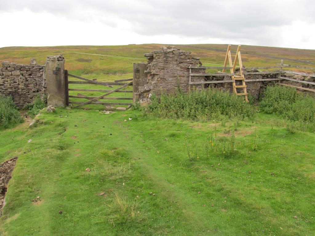
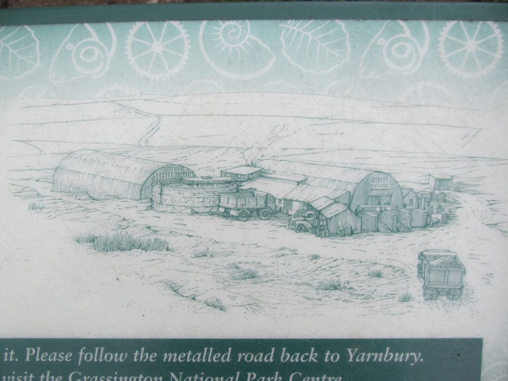
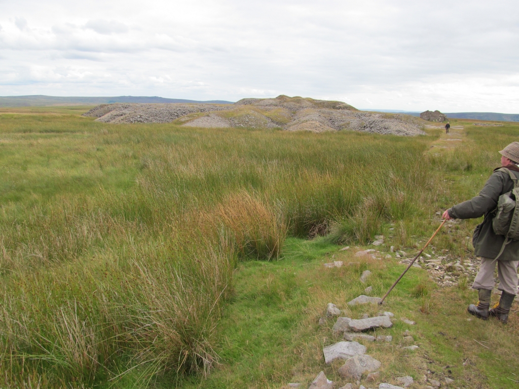
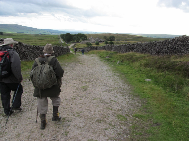
Along The Way:


Our third stop of the day was to the village of Haswell Plough to visit the site of Haswell Colliery (NZ 373422) which operated between 1833 and 1896. The colliery site was cleared some years ago but a substantial part of the pumping engine house remains and is still worth a visit.
Colliery Timeline:
1811 First sinking at Haswell proves coal exists underneath the magnesian limestone.
1831 Work begins on Engine Pit, but after digging through 54 ft of sand the pit is lost.
1833 The New Engine Pit is commenced at Haswell and is sunk down to the Hutton seam.
1834 After more than three years workmen employed in the sinking of Haswell colliery strike upon a fine seam of coal 504 feet below the surface
1835 – March 9th 200 workmen succeeded in winning the Hutton seam of coal, 5 feet 6 inches thick, at a depth of 930 feet from the surface.
1835 – July 2nd The first cargo of coals from Haswell colliery were shipped at Seaham. A public dinner was held in the afternoon, at the Lord Seaham Inn
1836 About eight miles of the eastern division of the Sunderland and Durham railway was opened. Several trains of wagons laden with coal traveled along a new line from Haswell colliery to Sunderland.
1844 The Haswell colliery mining disaster. 95 men and boys lost their lives.
1886 The Hutton seam is abandoned.
1895 Engine Pit closed.
1896 – Dec 31st Five Quarter, Main Coal, and Low Main seams are abandoned. The colliery is closed due to being unprofitable to work.
Interesting Fact:
Haswell Colliery can also lay claim to being the site where the first steel cable ever to be used down a mine shaft was deployed.
Historic Photos
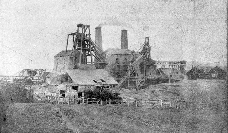
The following photograph was taken 20.05.1864.
The pumping engine house is to the left of the two chimneys.
Another from 1943.

A few more from around 1960 before landscaping.


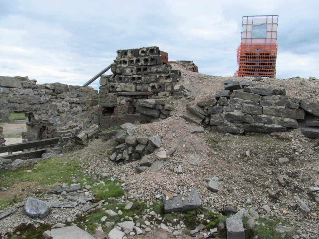
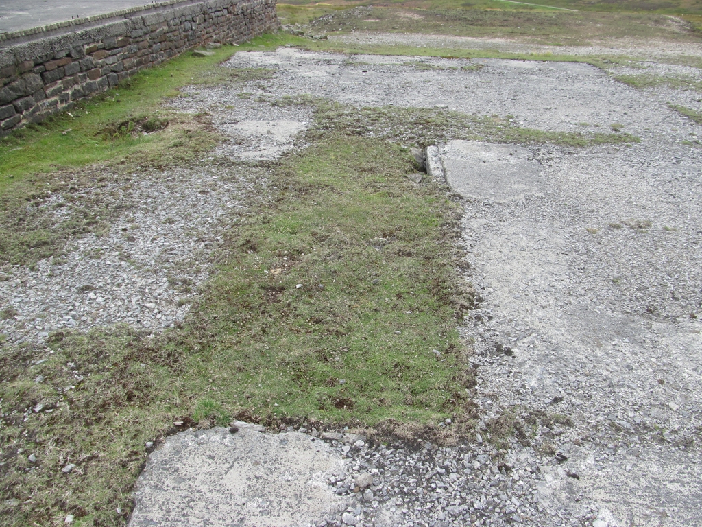
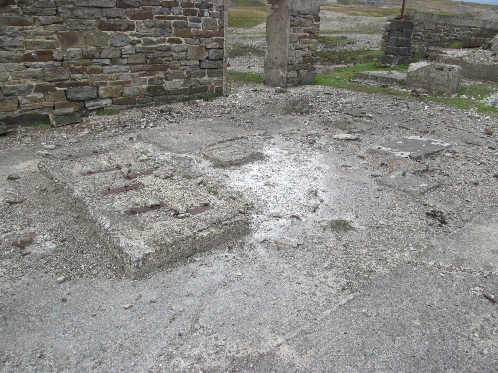
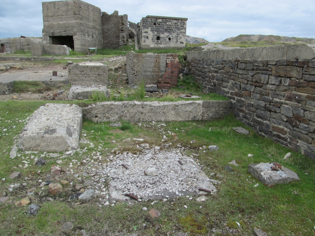
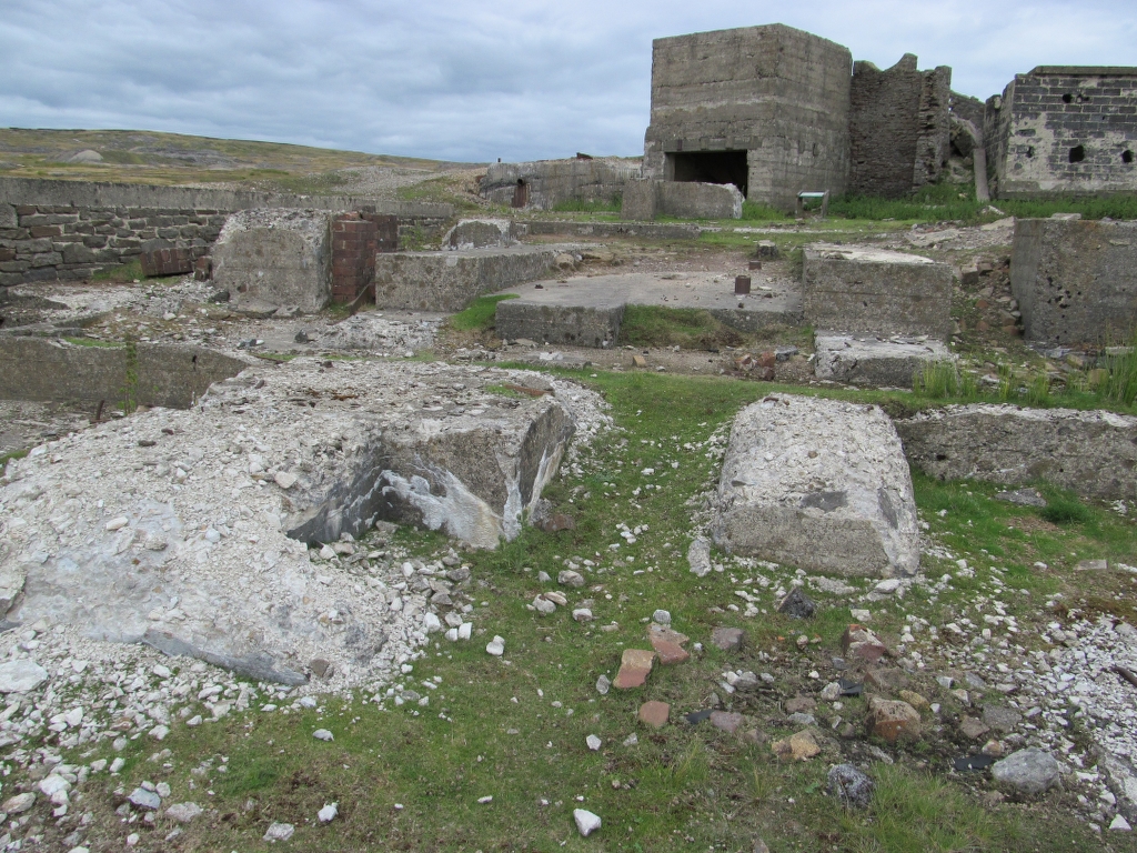
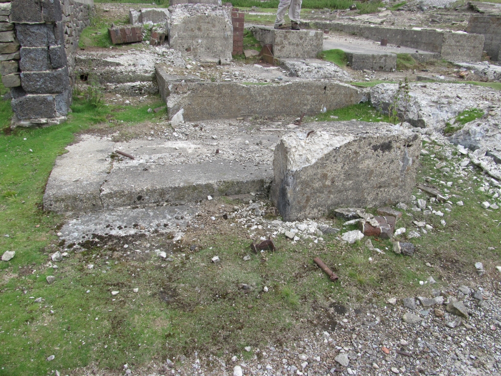
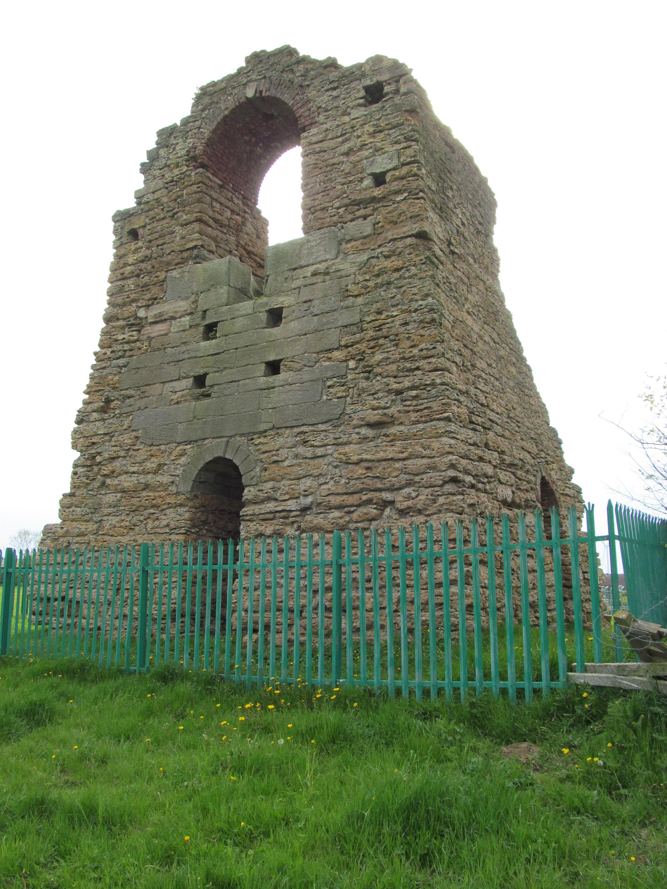
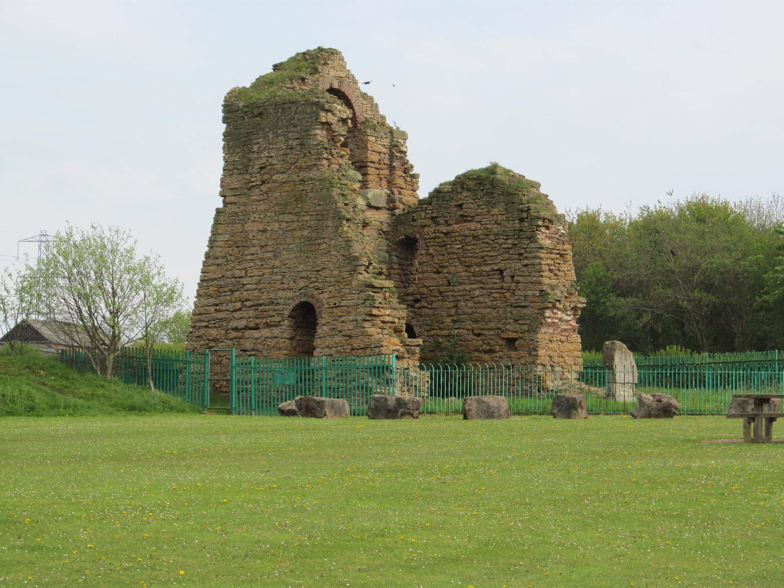
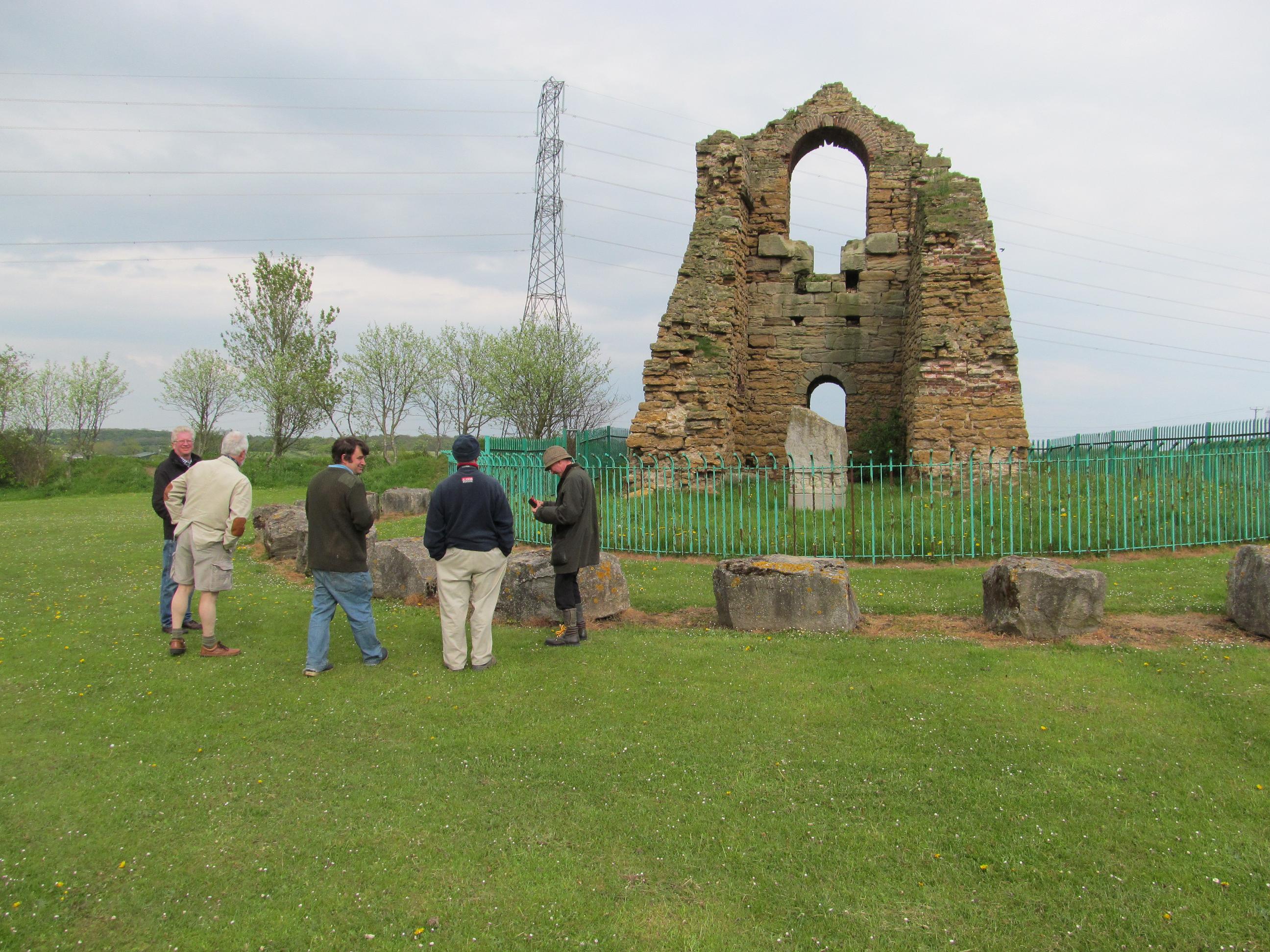
The Site Today:
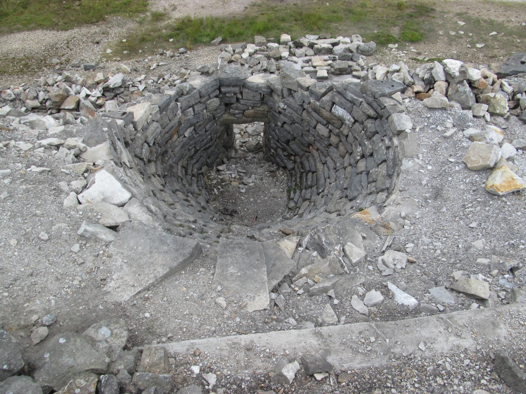
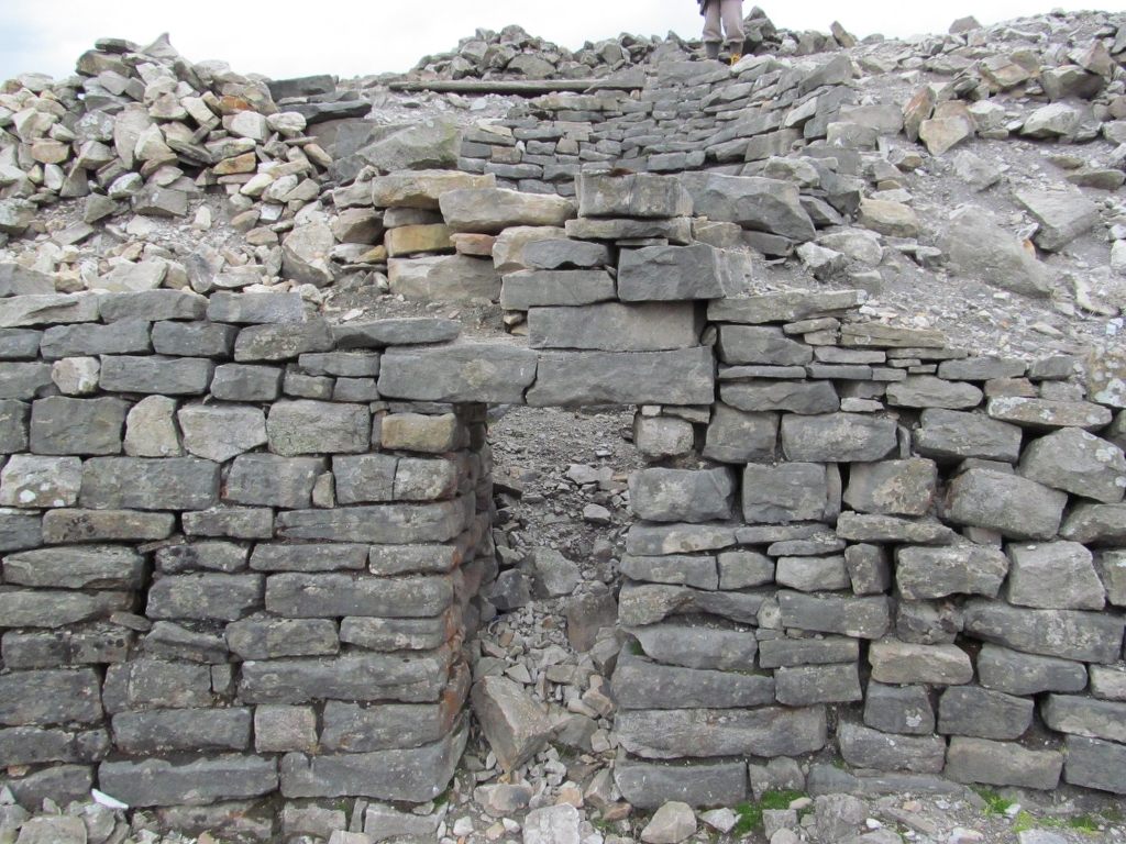
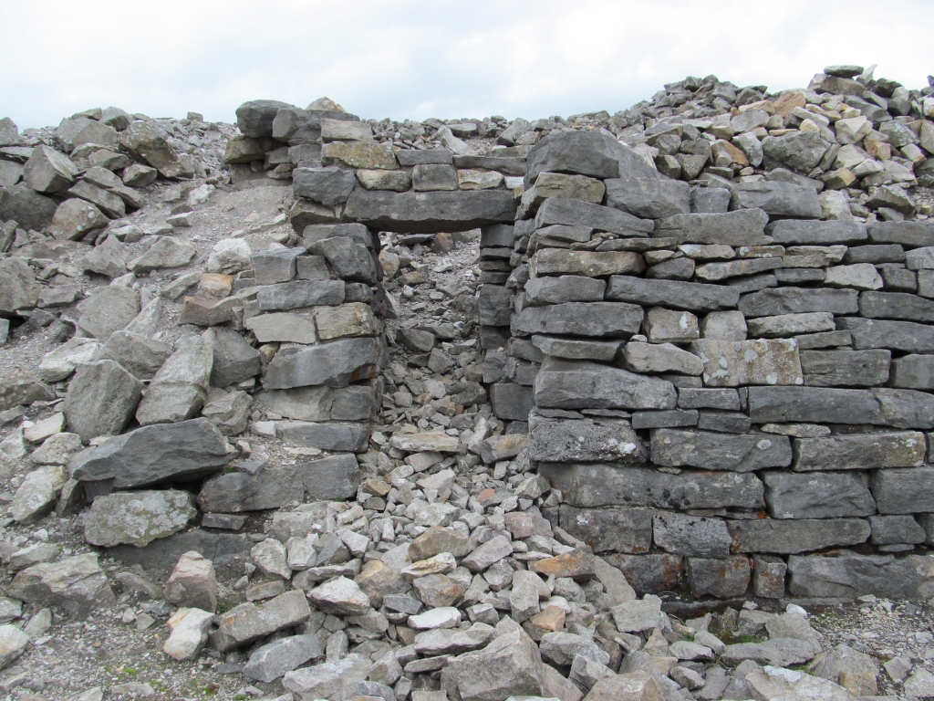
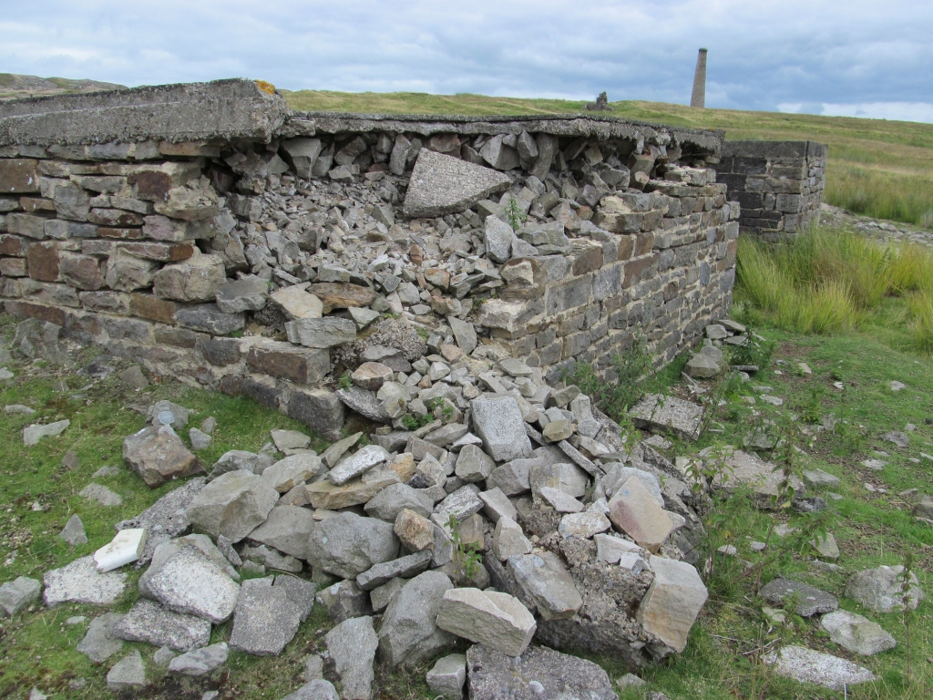
Even though most of the pumping engine house has been demolished and buried following the landscaping of the site the front Bob wall adjacent to the shaft is still very interesting to look at. It has largely been constructed of local limestone but the mounting block for the beam itself is made of imported sandstone which is harder and would take the weight and motion of the beam better.


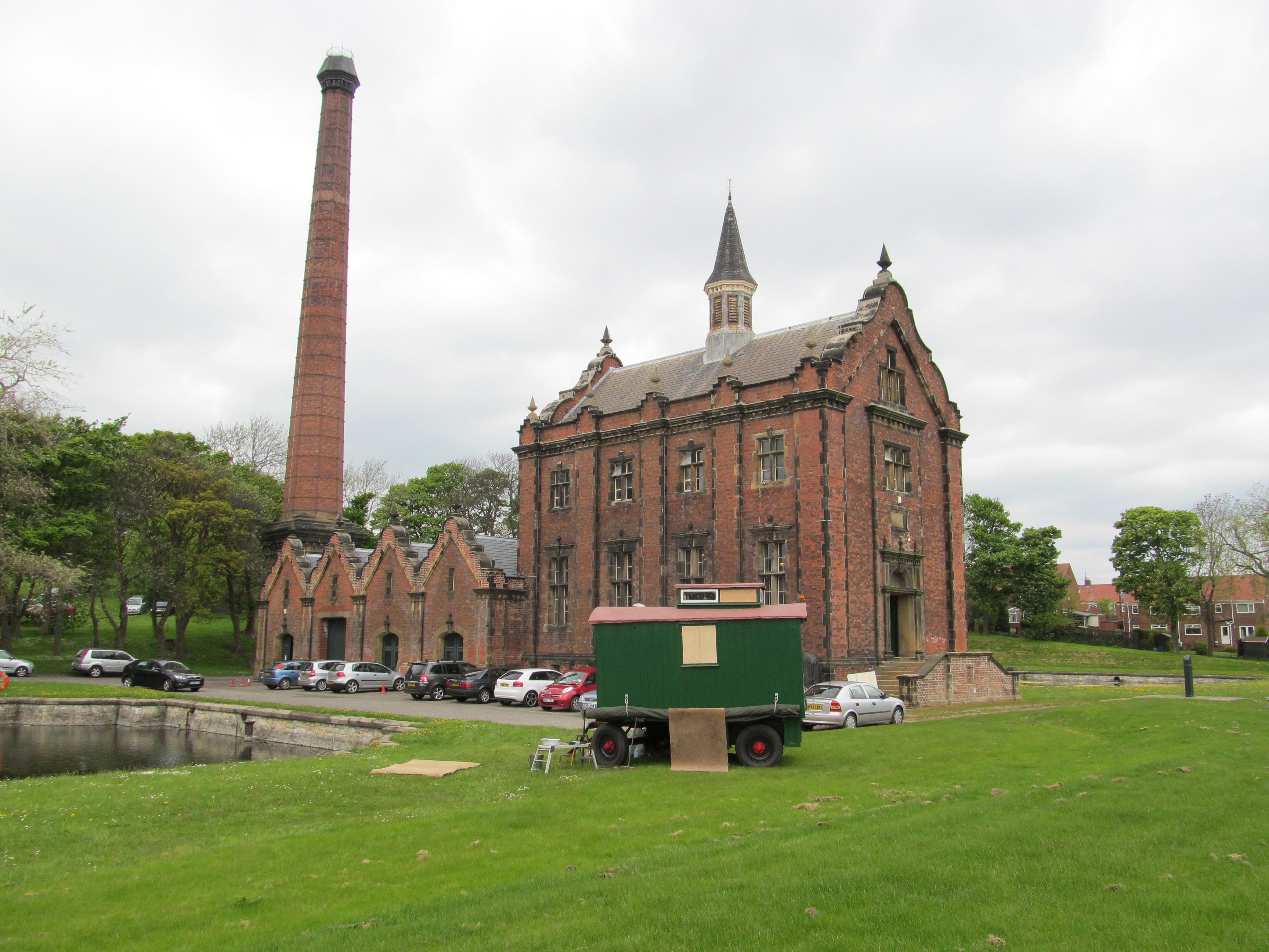
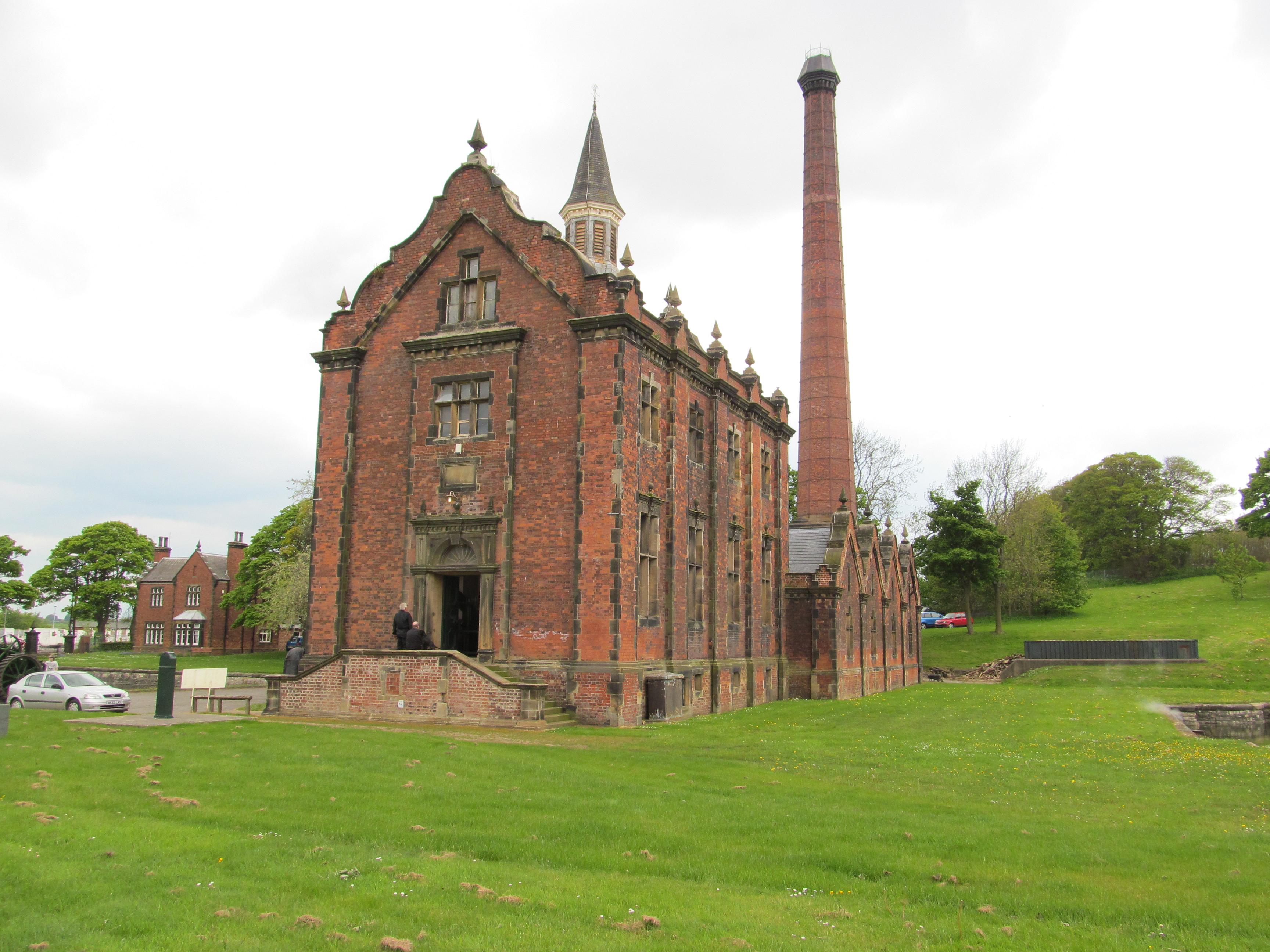
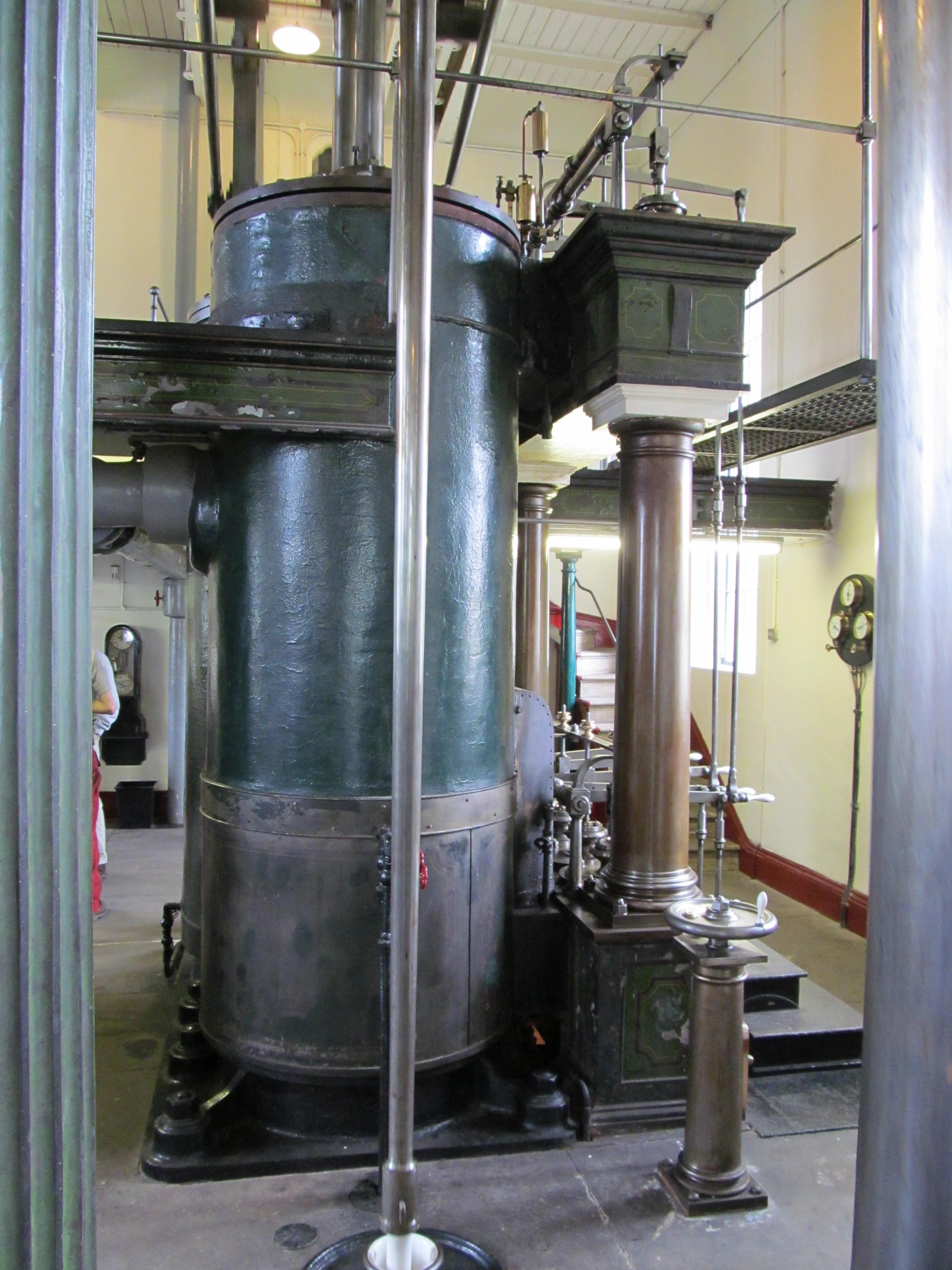
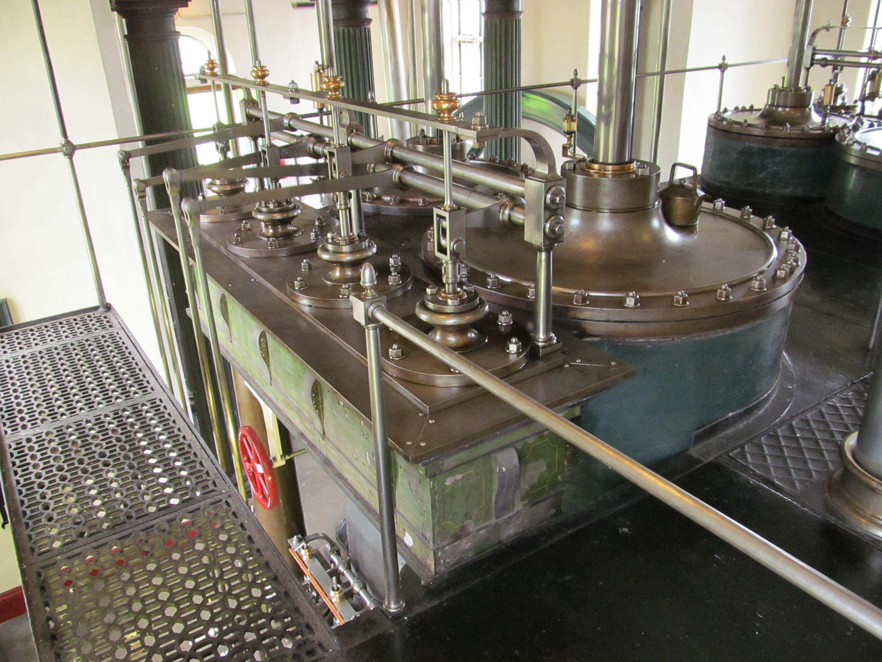
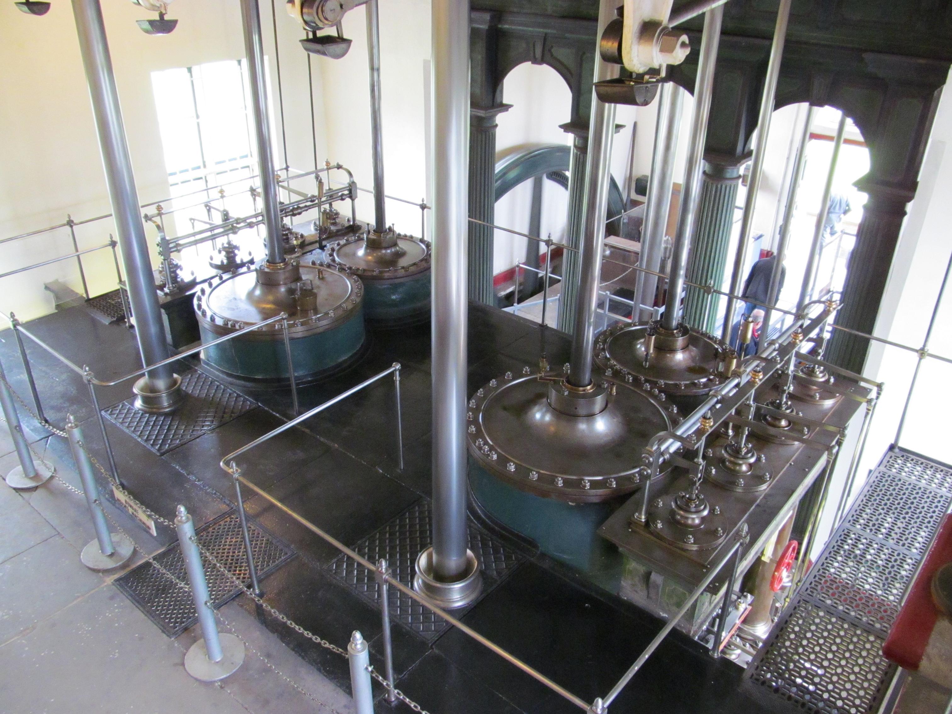
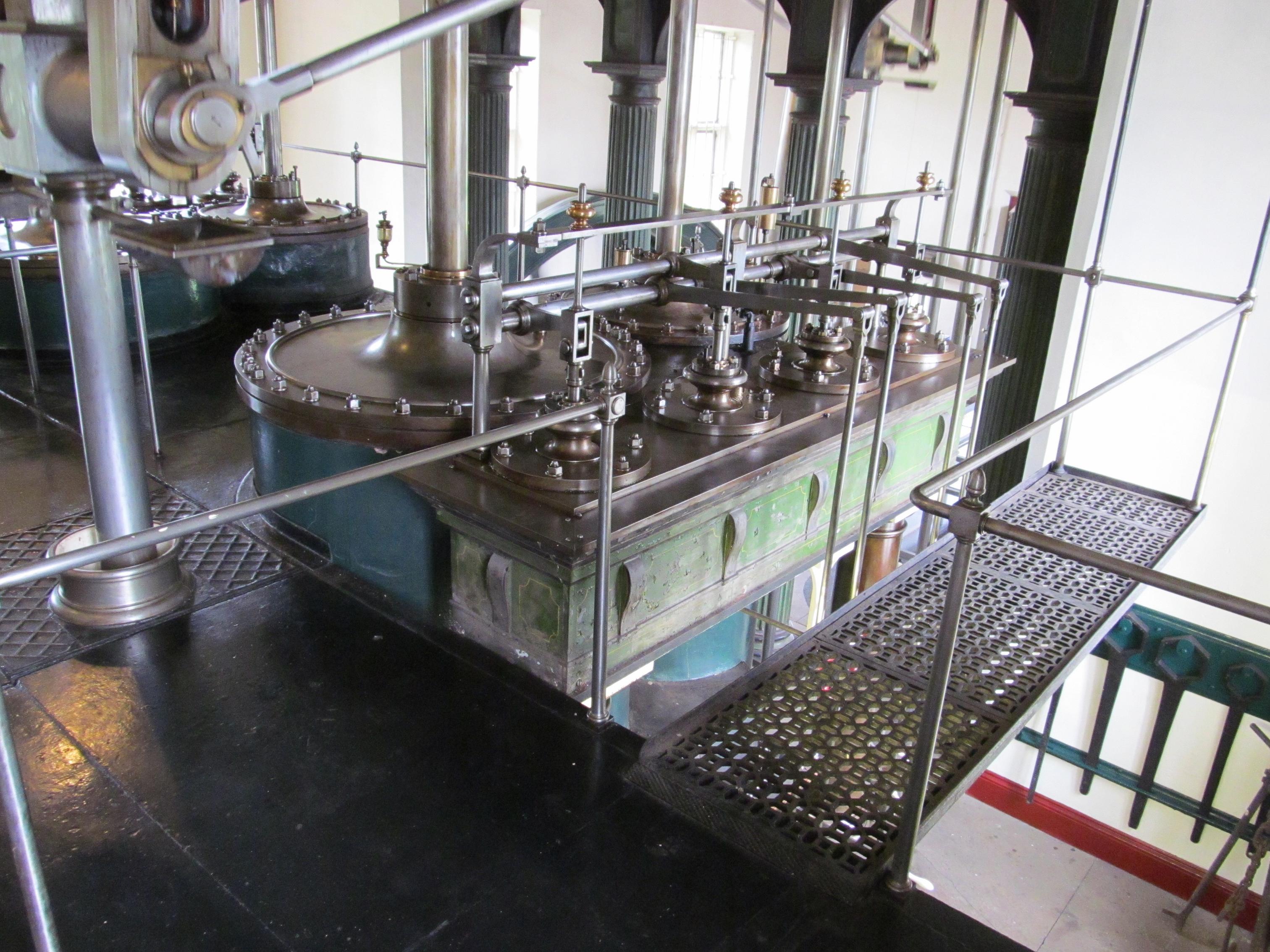
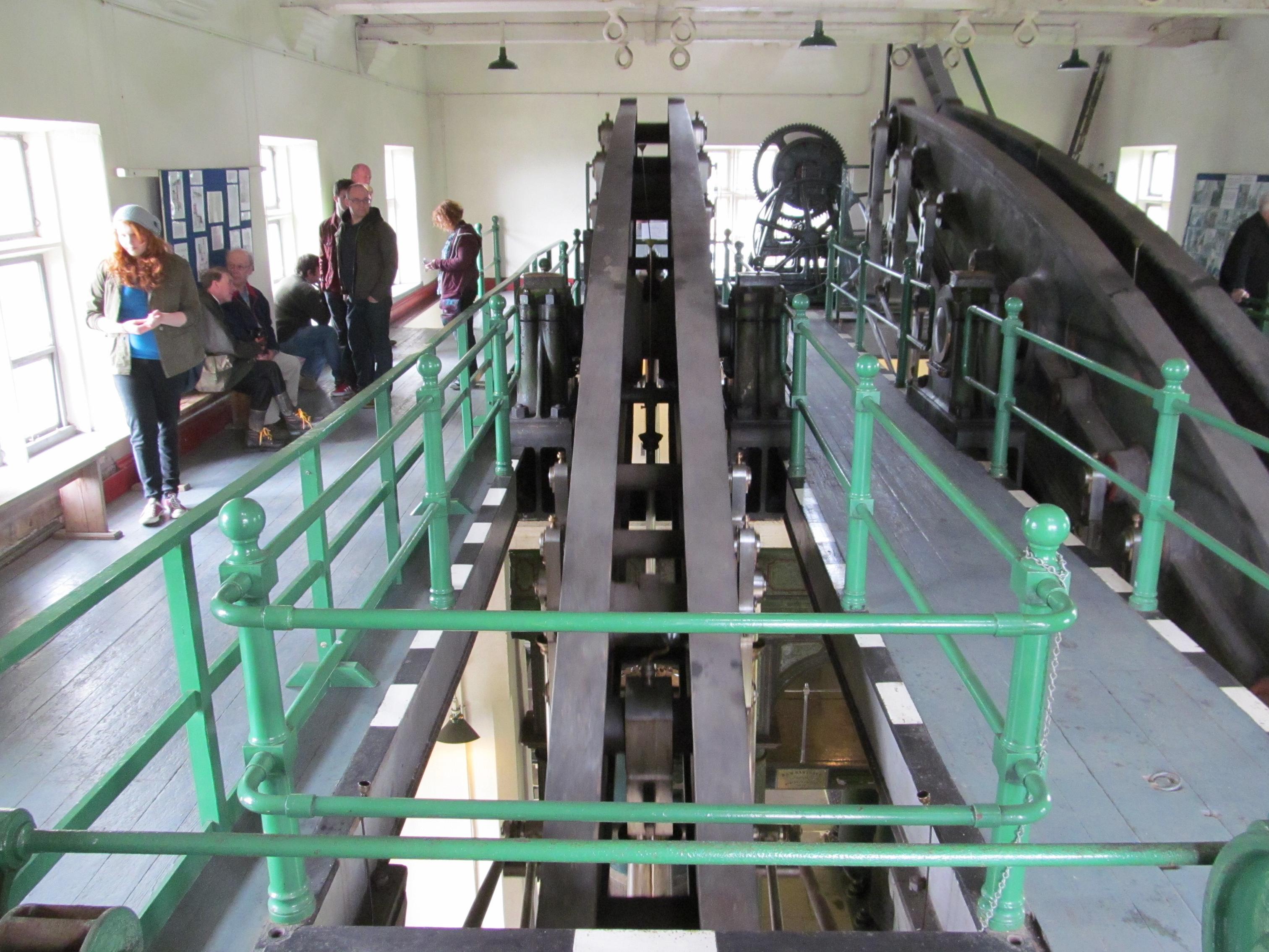
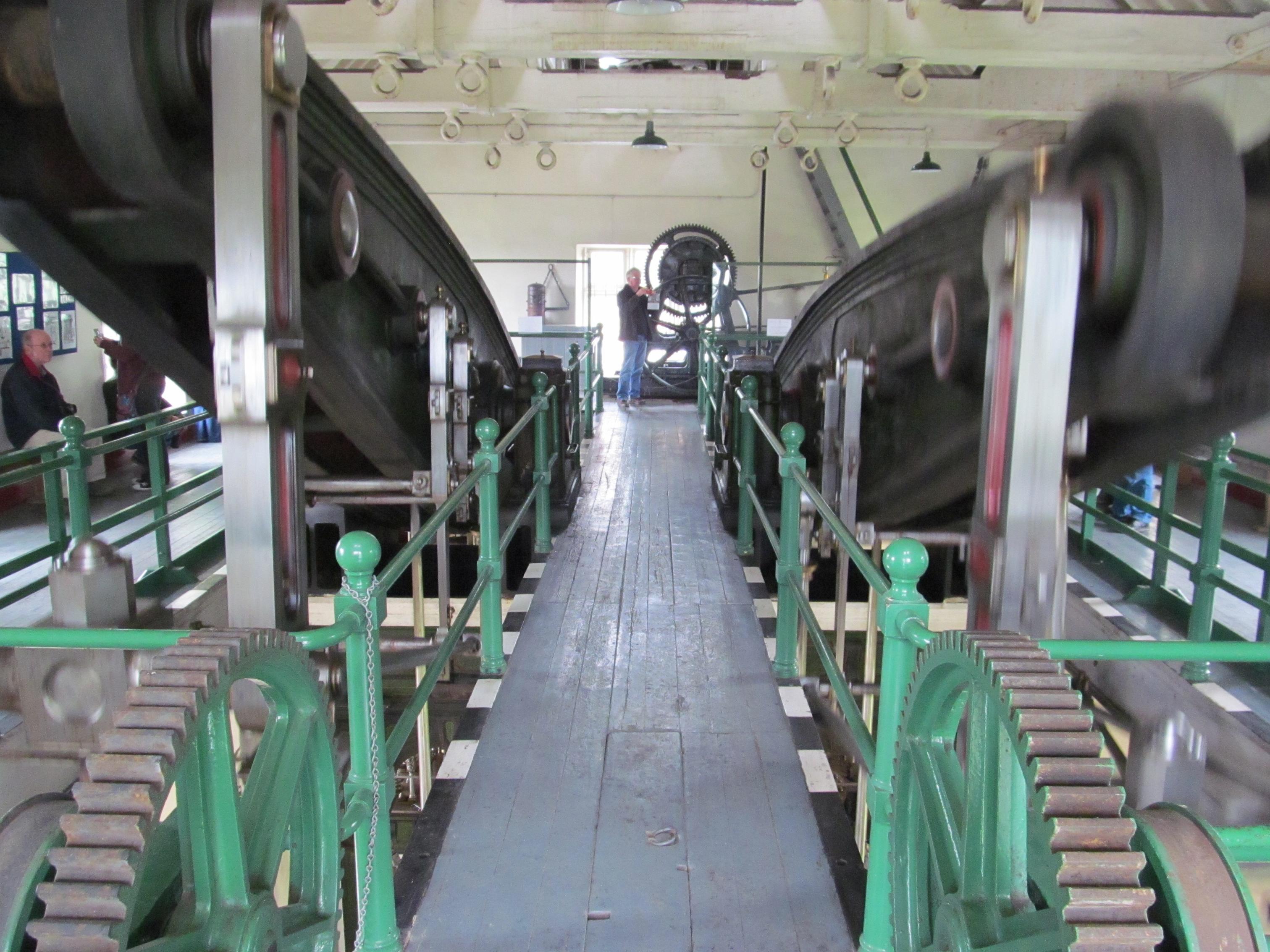
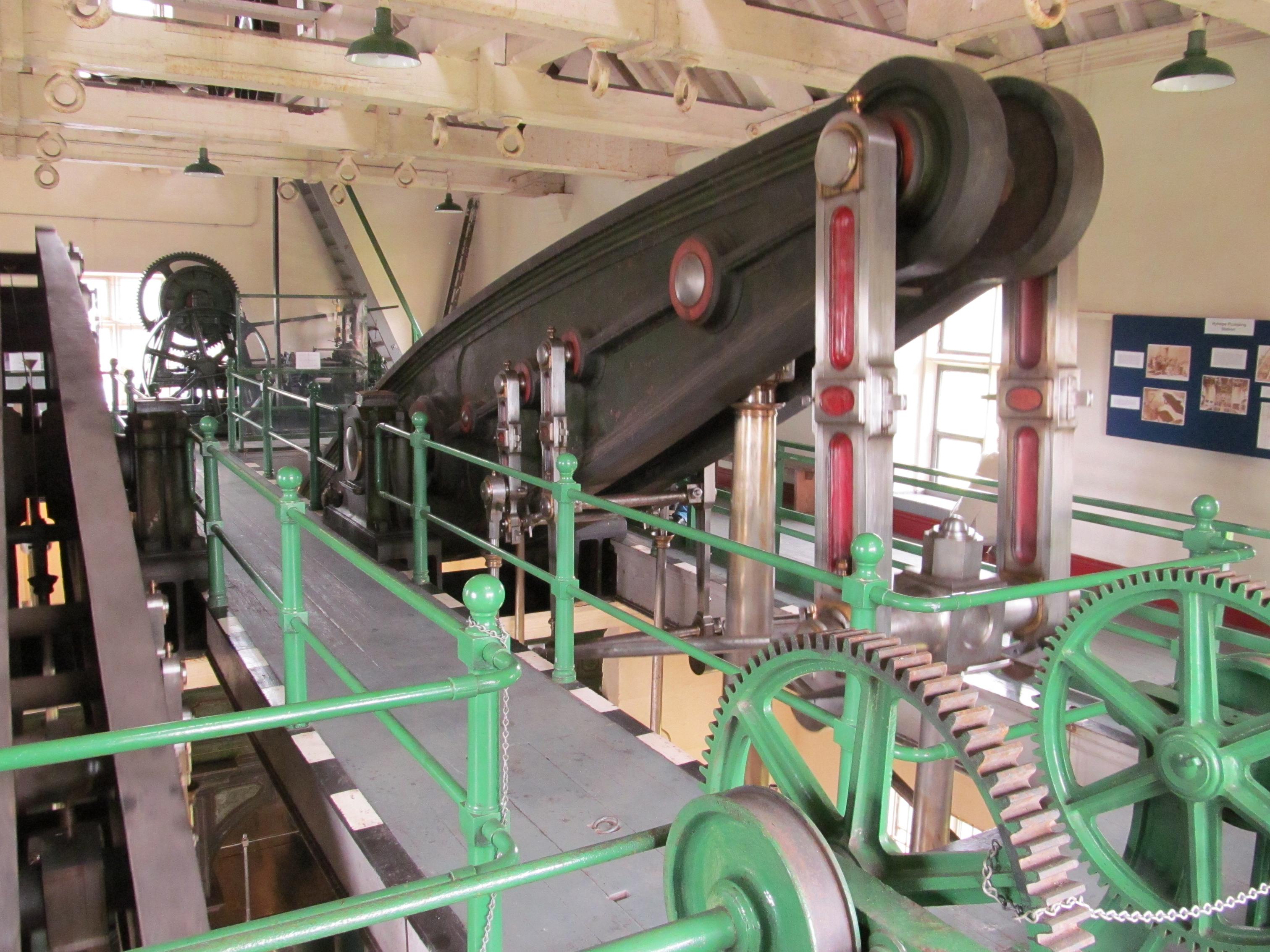
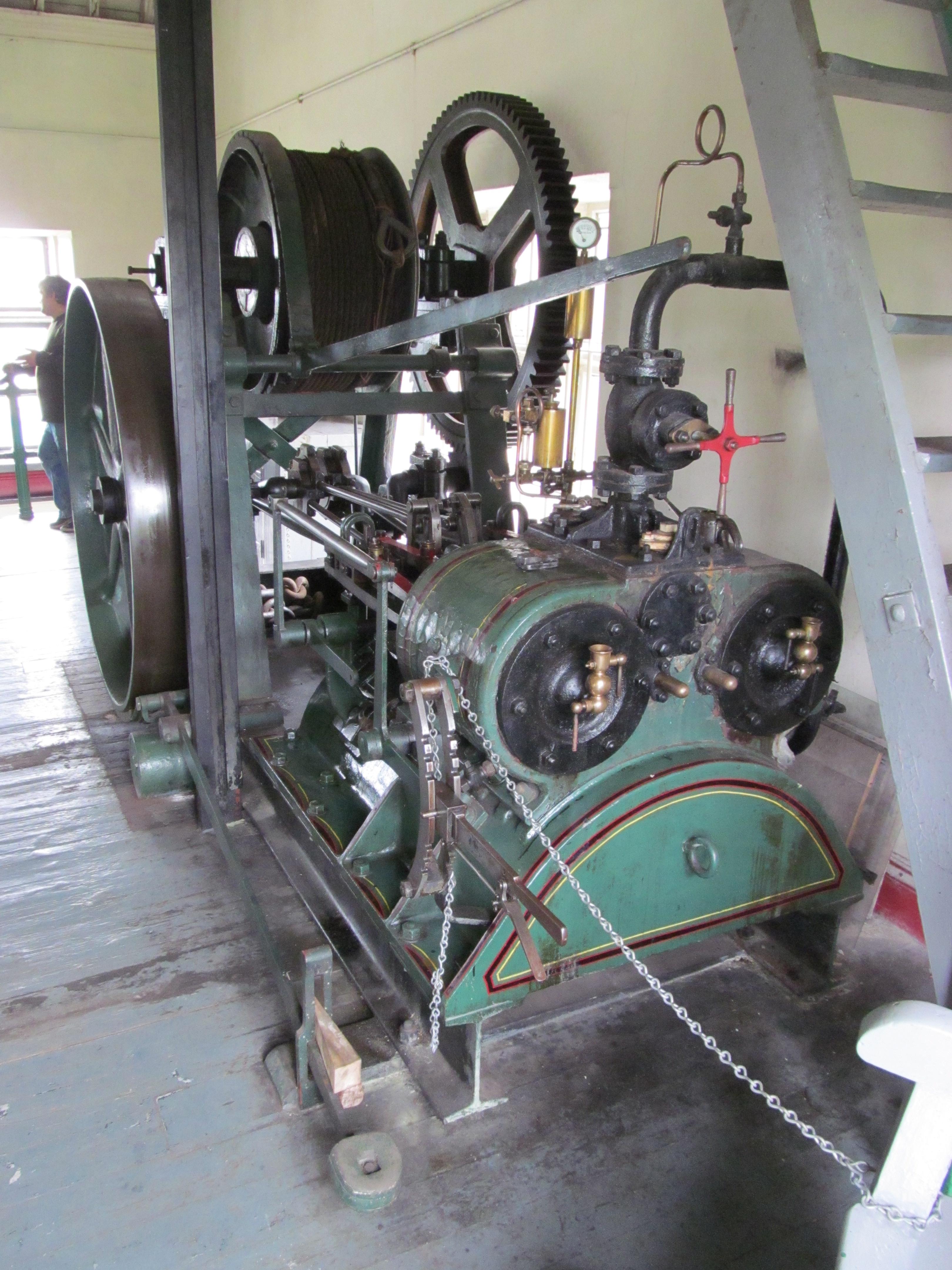
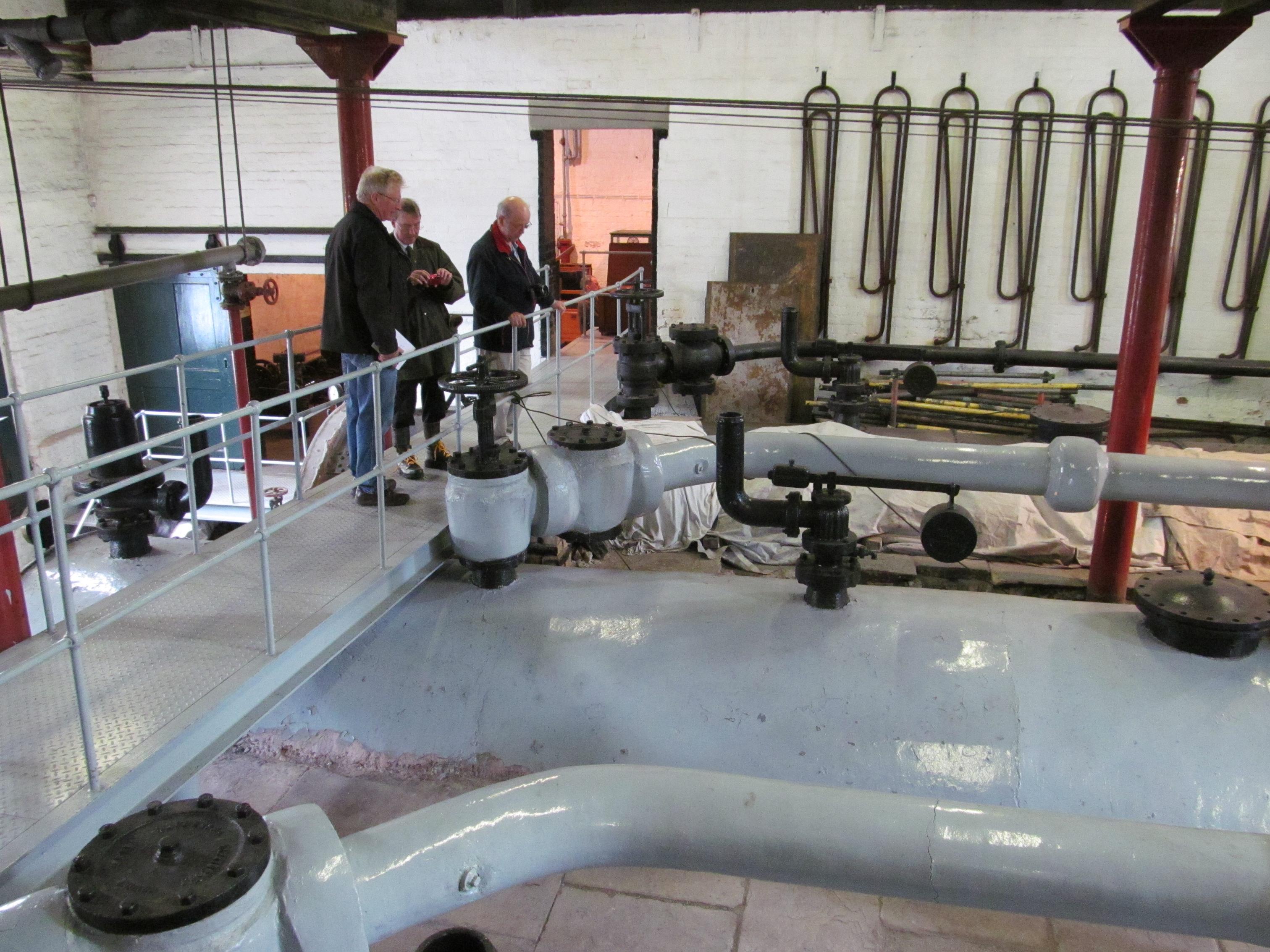
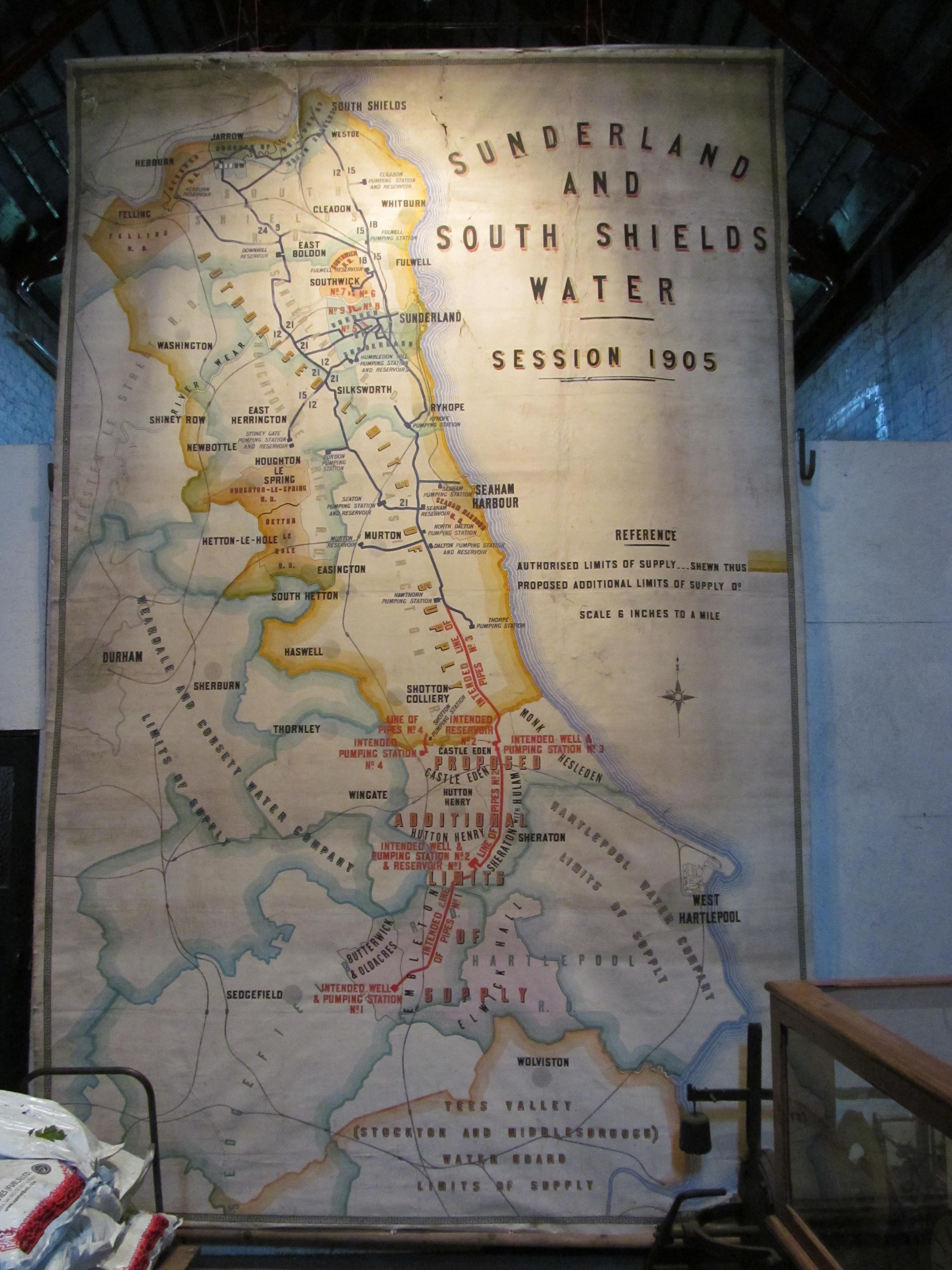
The Ryhope Engines Museum is based at Ryhope Pumping Station which was built in 1868 to supply water to the Sunderland area. The station ceased operation in 1967 – after 100 years of continuous use.
Background
As the Industrial Revolution developed new challenges were thrown up. A rapidly growing population in the nineteenth century, much of which was concentrated in new mining villages throughout the Northumberland and Durham coalfield, together with the growth of new industries and expansion of older ones in towns like Sunderland (now a city), produced a rapidly increasing demand for water for domestic and industrial requirements.
Various sources were used to meet this demand. Rivers, natural springs, surface reservoirs and wells were used. In North East Durham, however, abundant supplies of good quality water were on the doorstep, or, more correctly, in the cellar, for it lay within the geological stratum known as magnesian limestone.
During the first half of the nineteenth century repeated cholera outbreaks, both nationally and locally led to a much greater concern for water supplies. The creation of the Sunderland and South Shields Water Company in 1852 was one local result of this.
The Construction
At the time the Company received the Royal Assent there were several pumping stations in districts around Sunderland but the urgency of water demands pressed heavily upon the Company. In 1864 four acres of land at Ryhope were acquired and in May of the following year Thomas Hawksley, in his position as Engineer to the Company, was asked to provide designs and specifications for the ‘new works’.
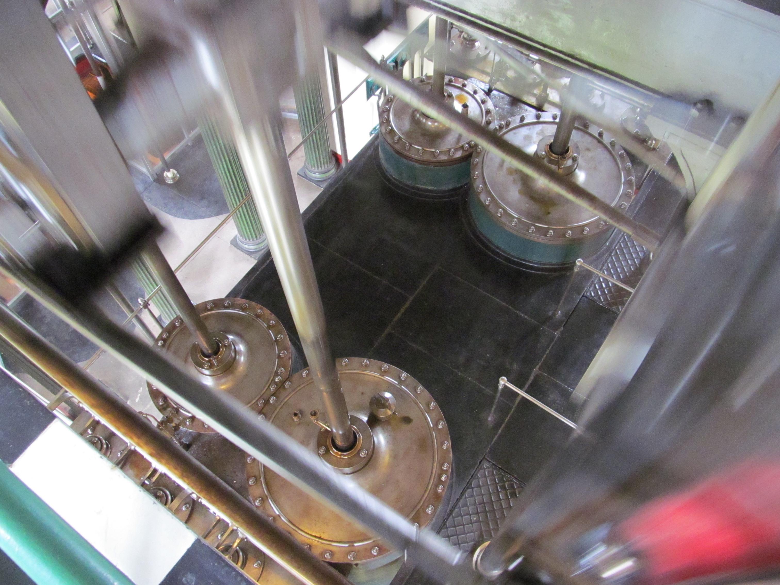
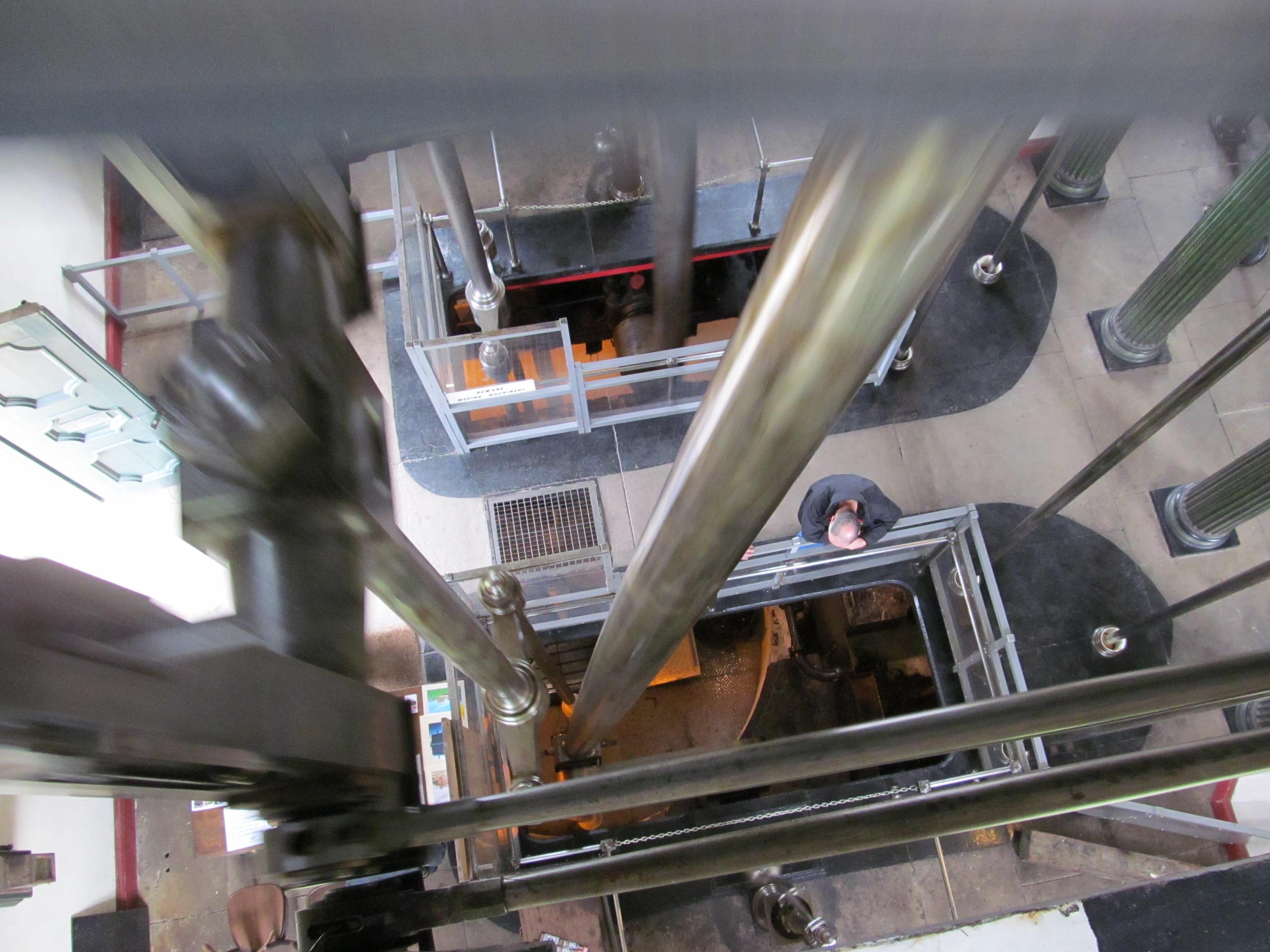
Construction of the engine house was not without its problems. The beam engines and their house form an integrated structure. Not only did the foundations have to serve as foundations for most of the engine components, as well as provide support for the well heads, but also the massive rocking beams had to be supported at some twenty-two feet above ground level. Therefore engine and engine house construction had to proceed together, but not in such a manner that they would interfere with the sinking of the wells.
The Exterior


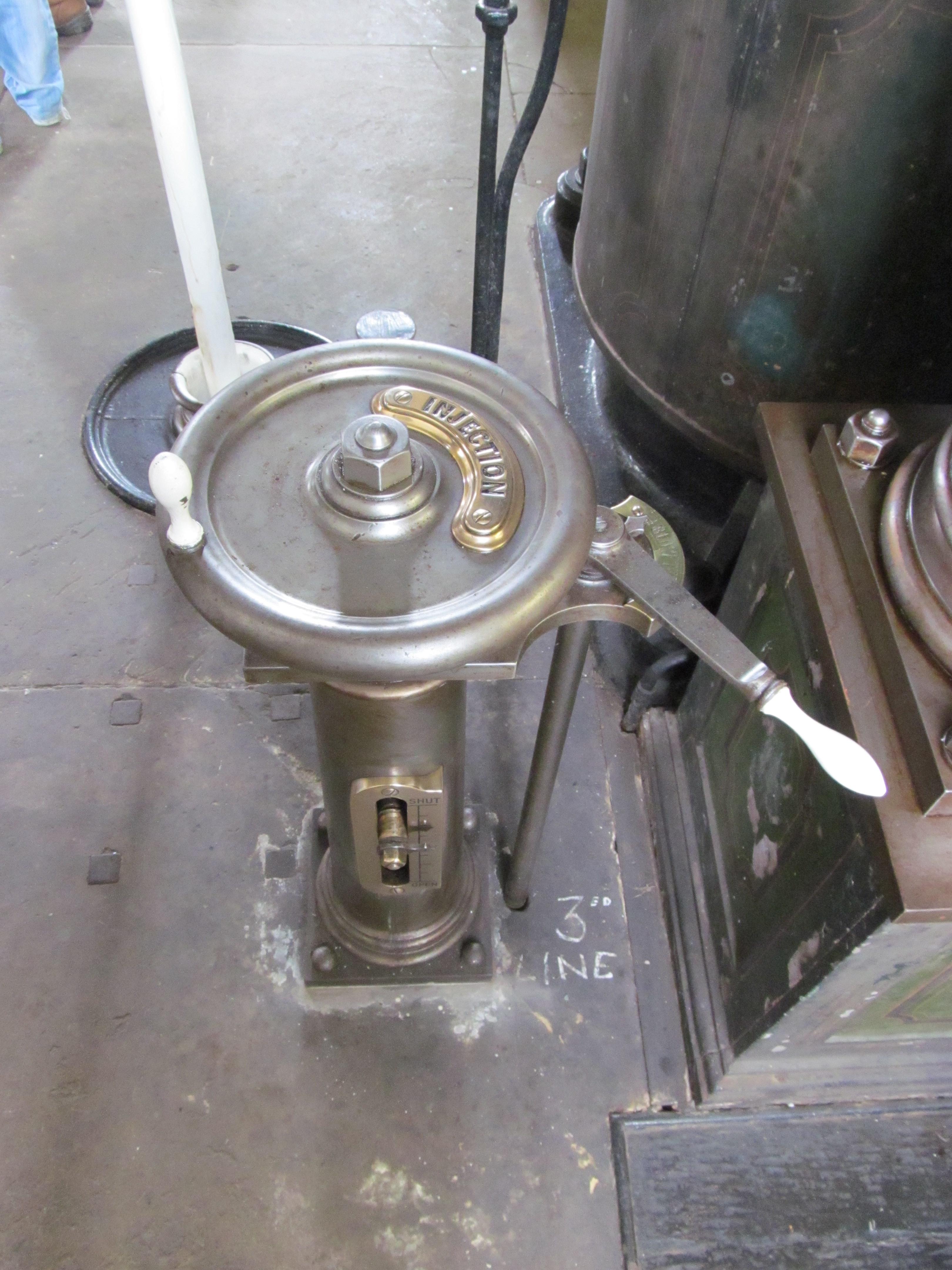
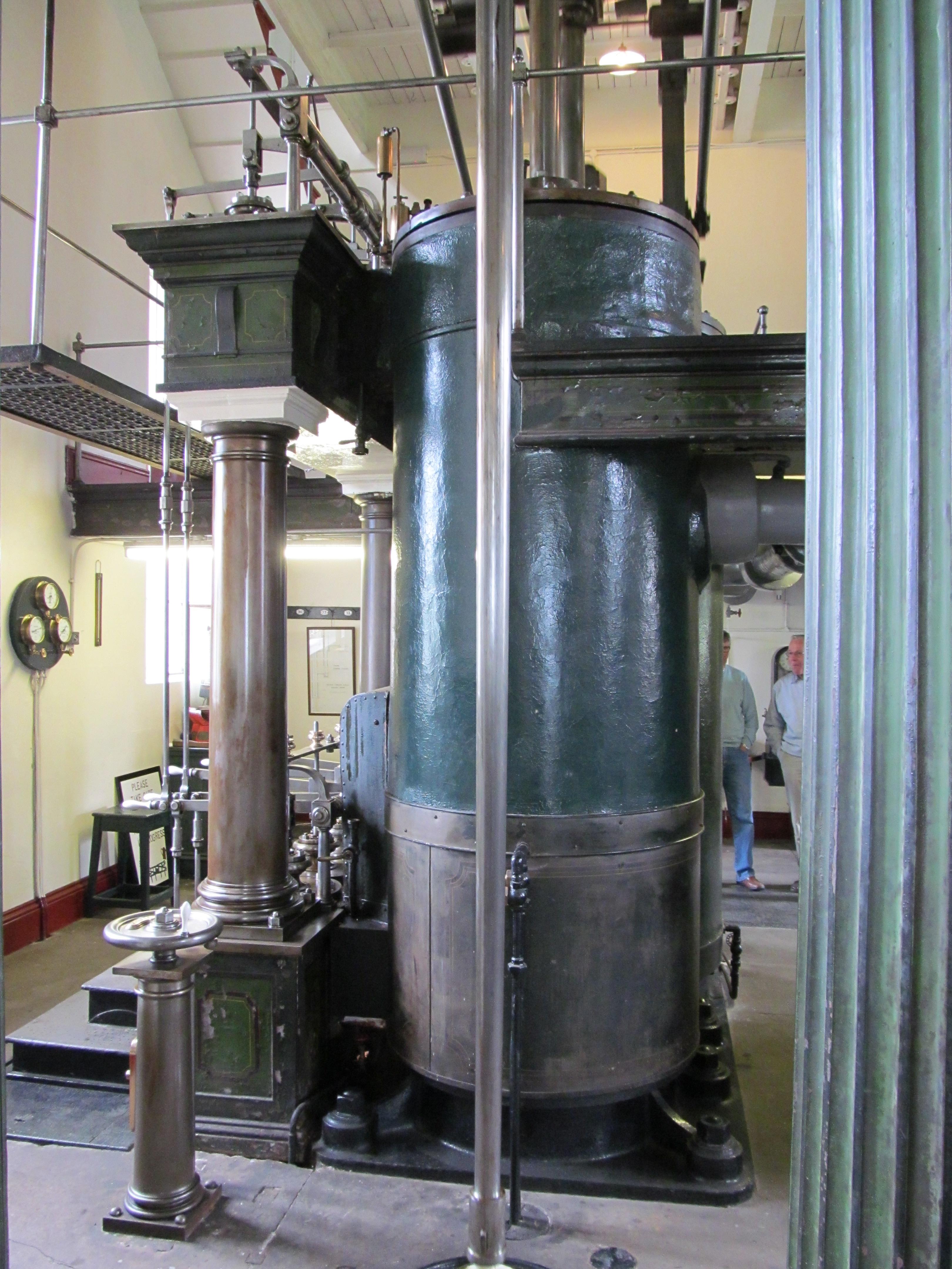
Ground Floor

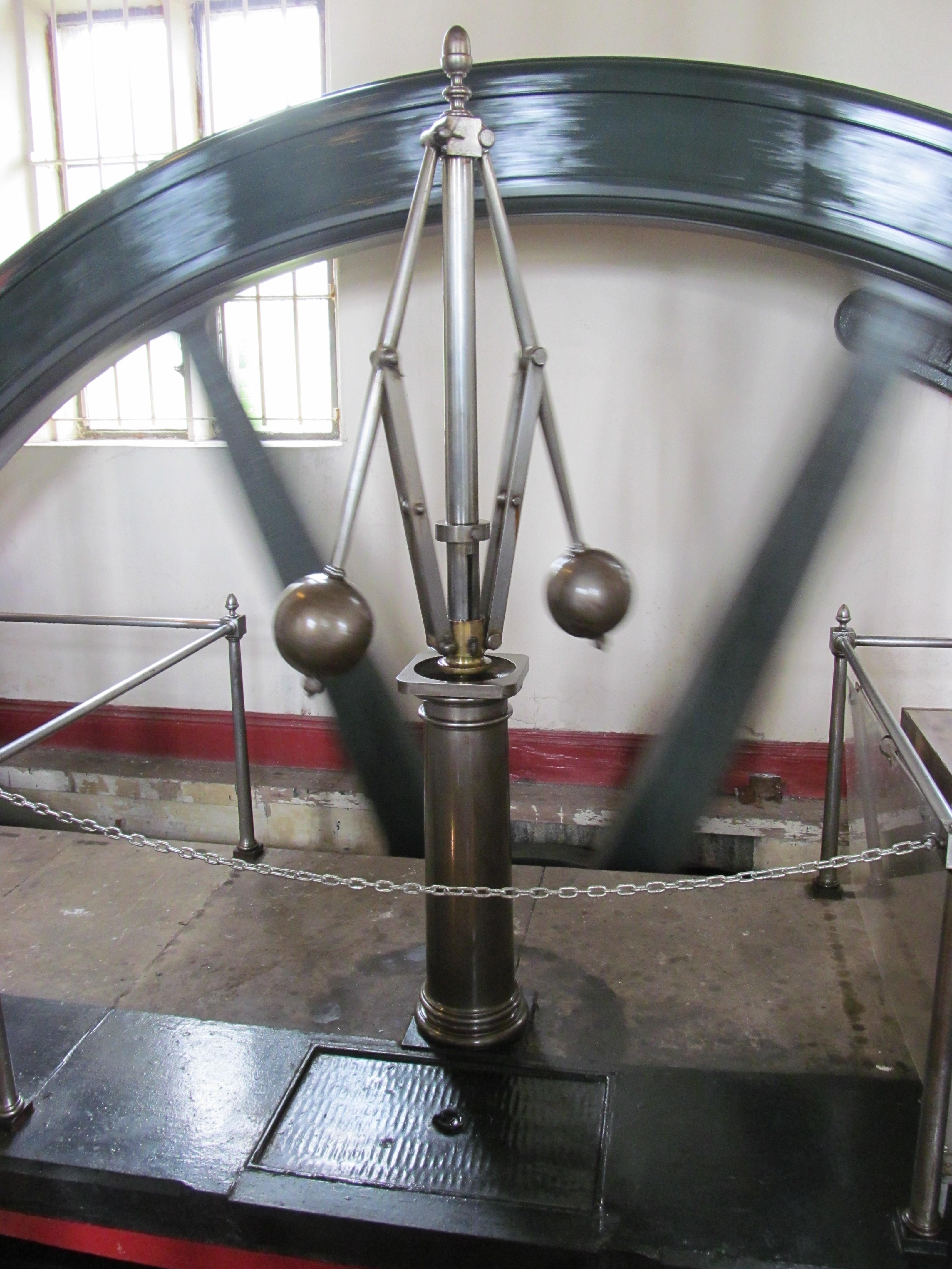


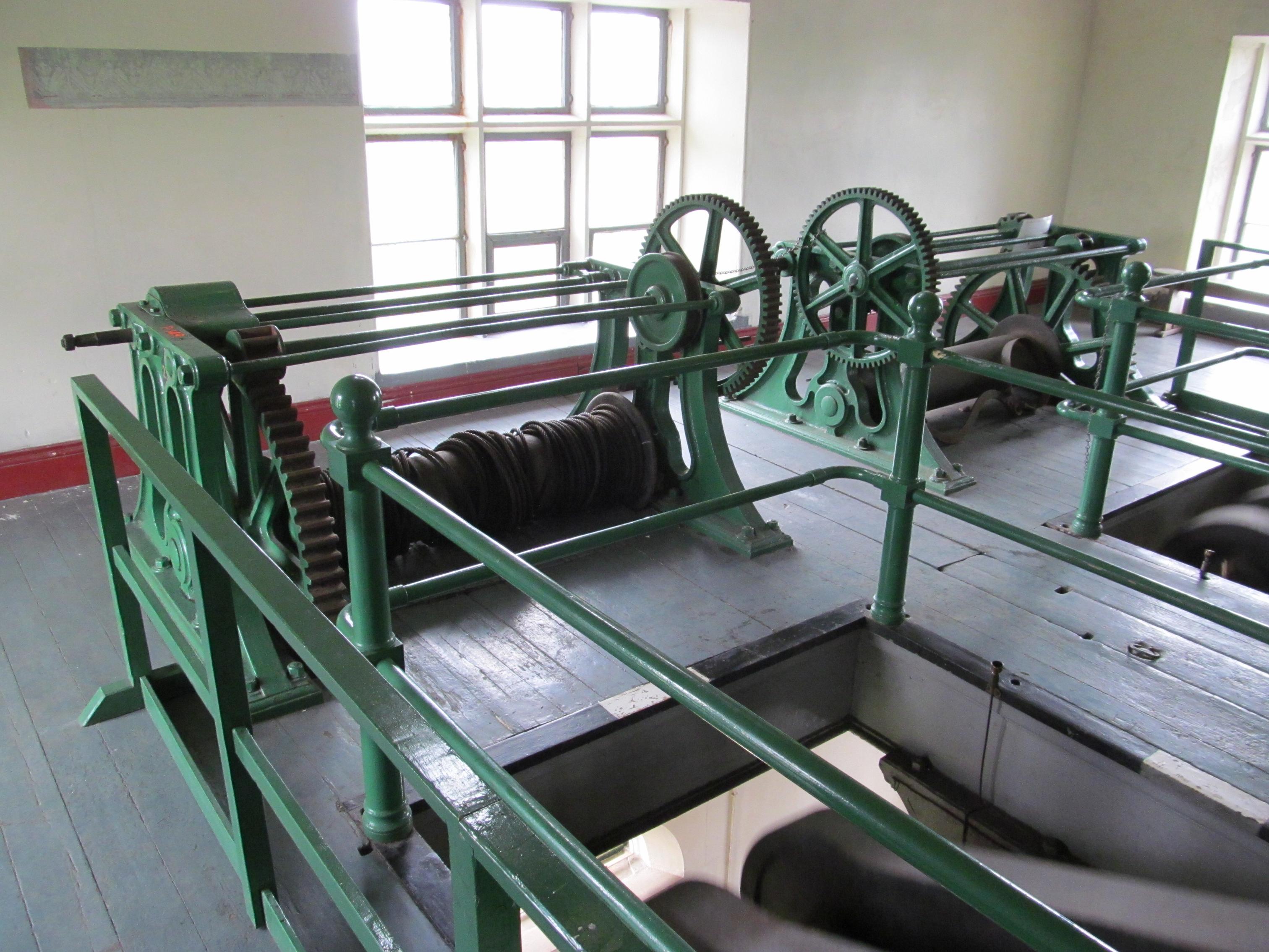
The First Floor

The Second Floor


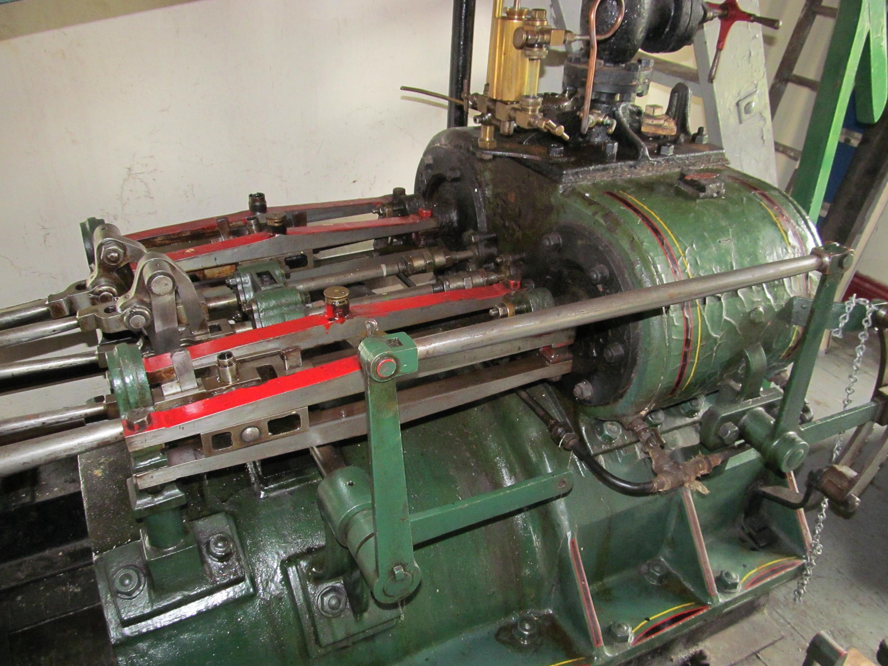
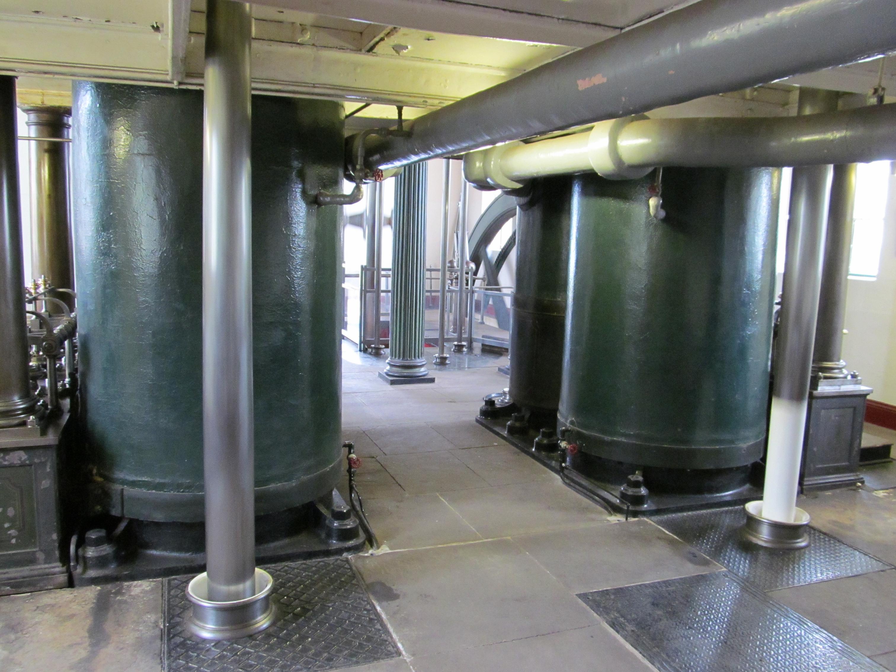
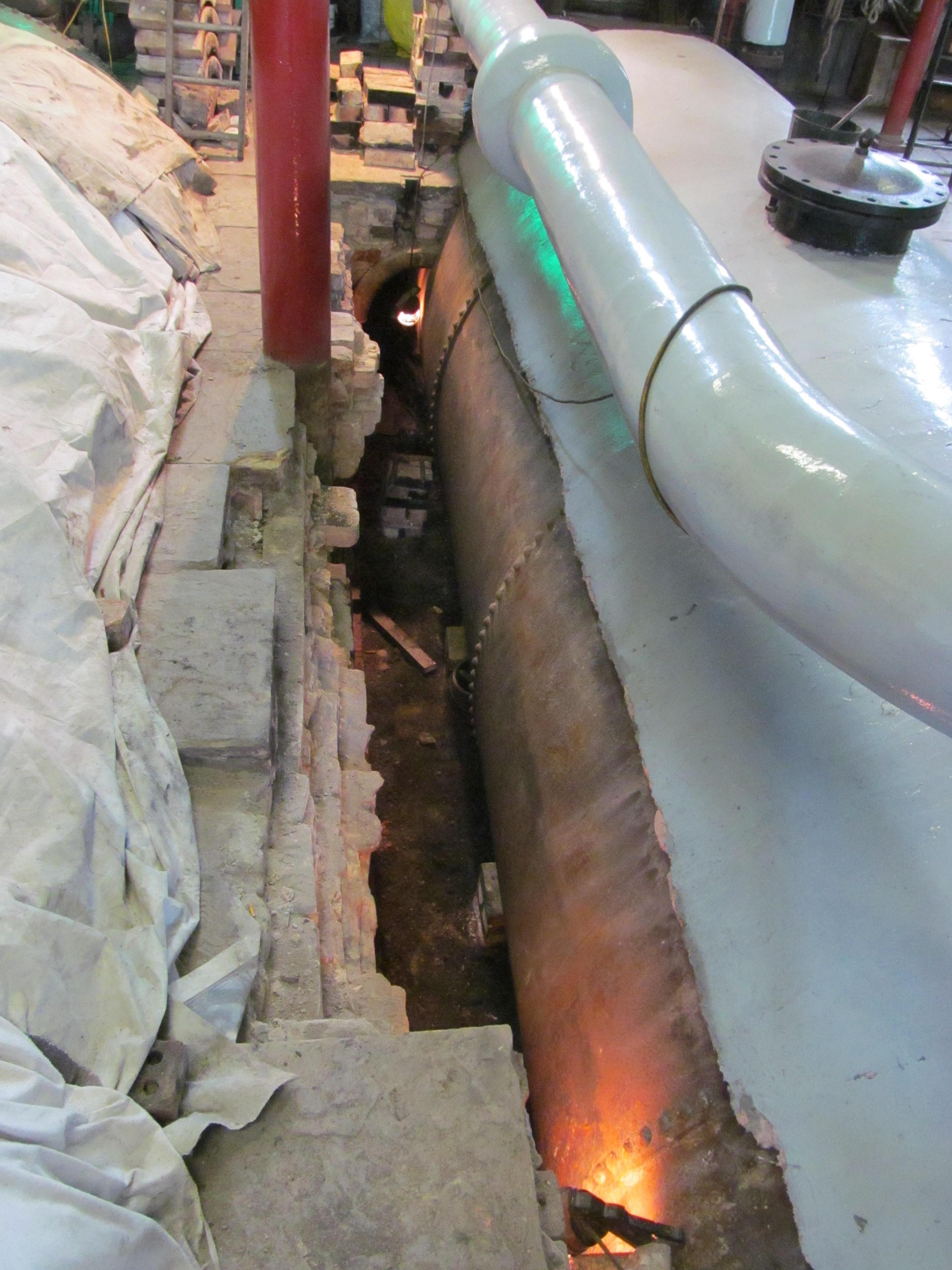
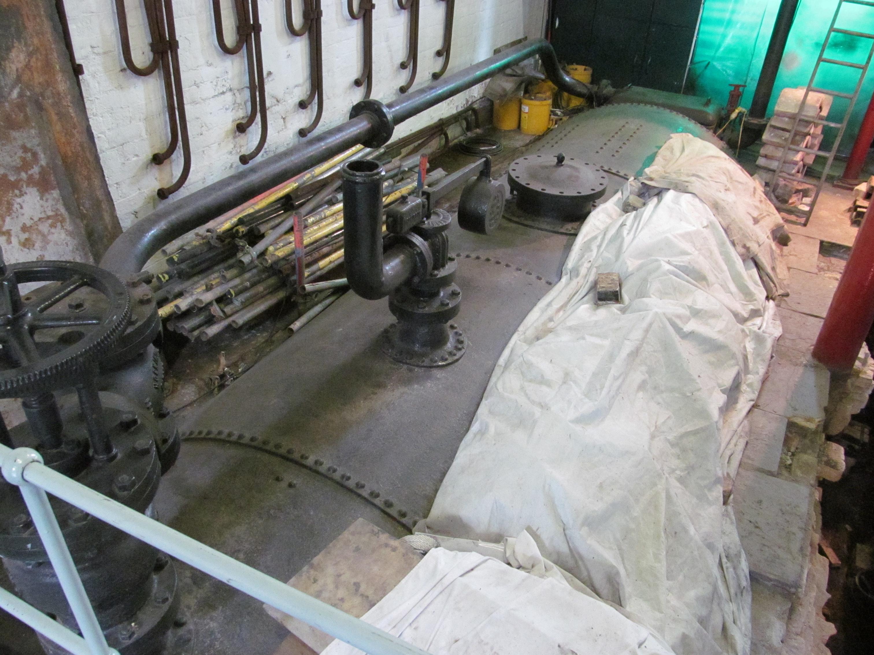
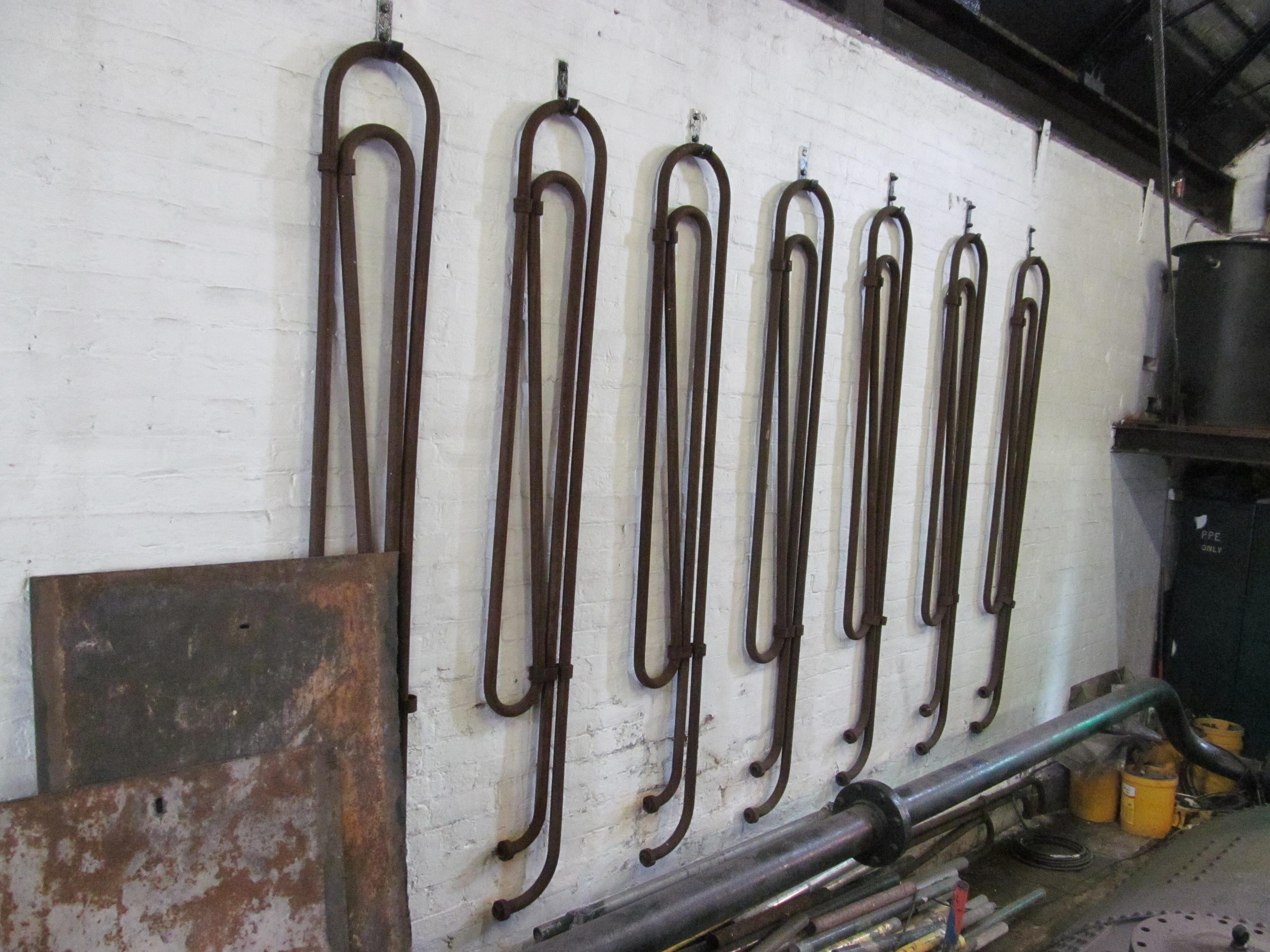
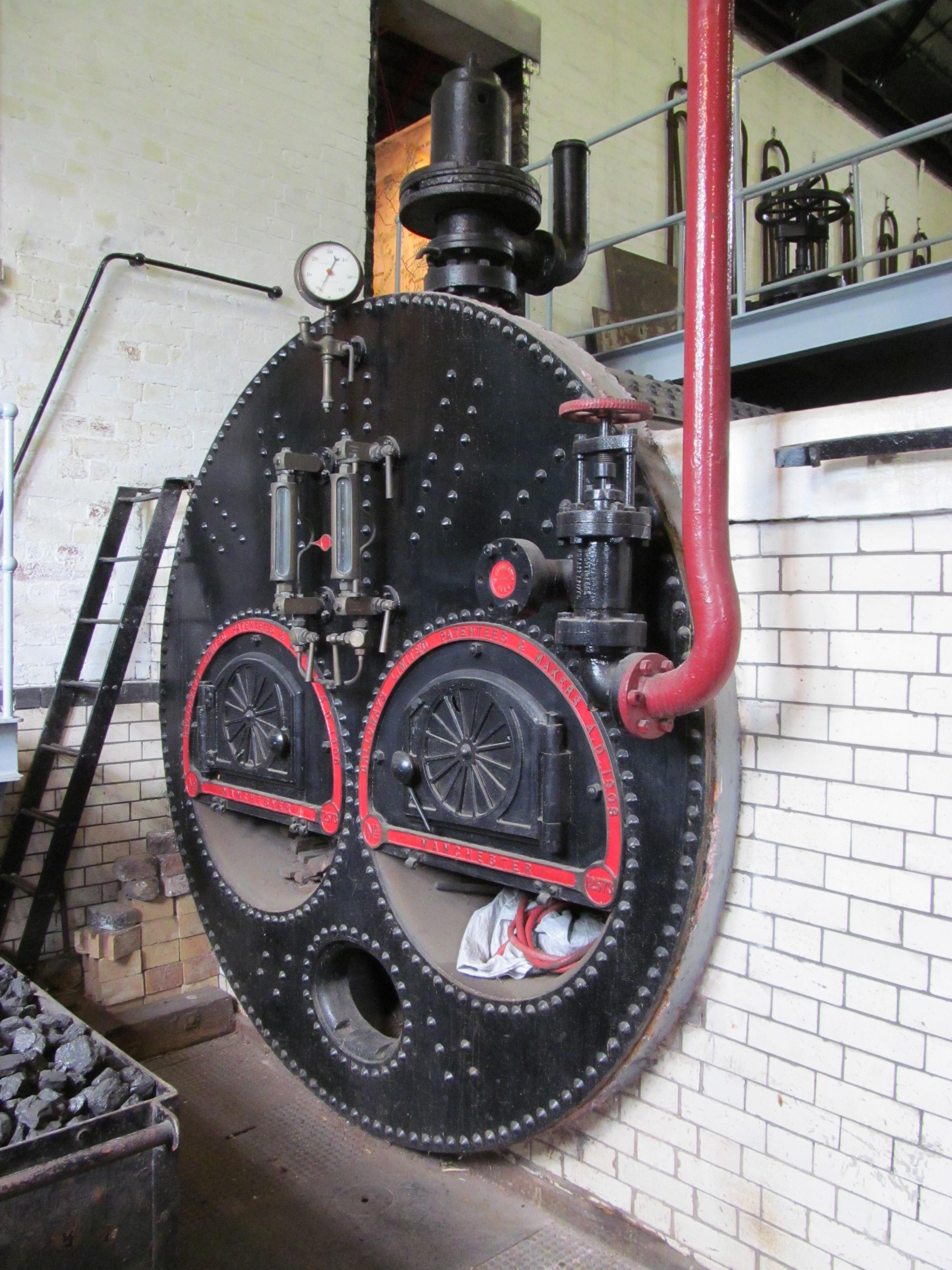
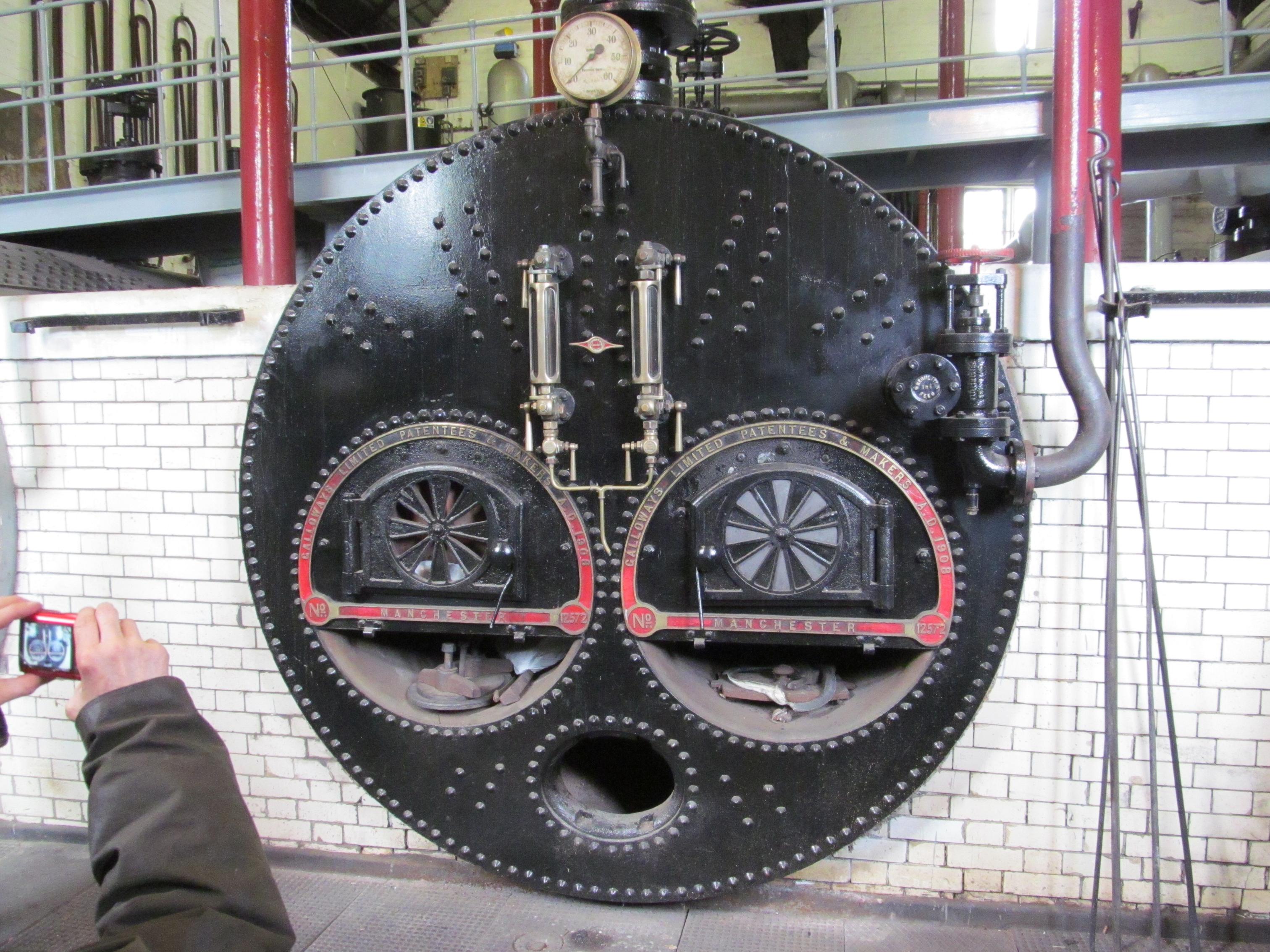
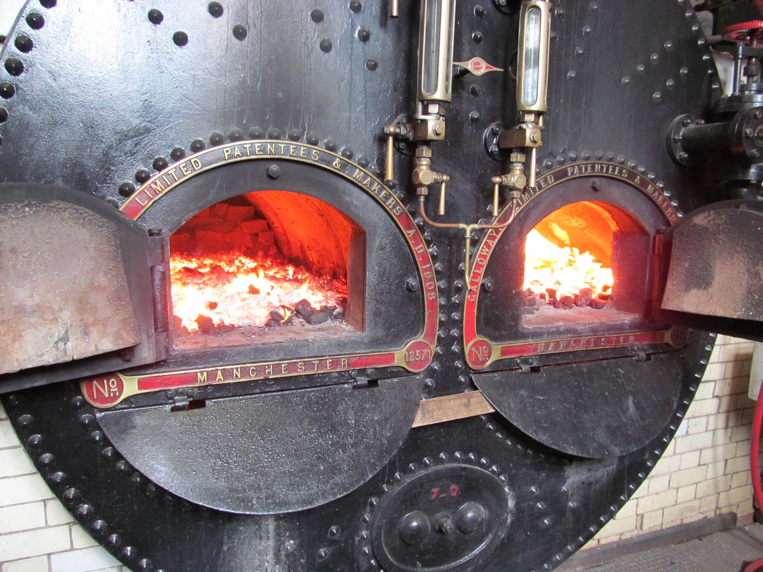
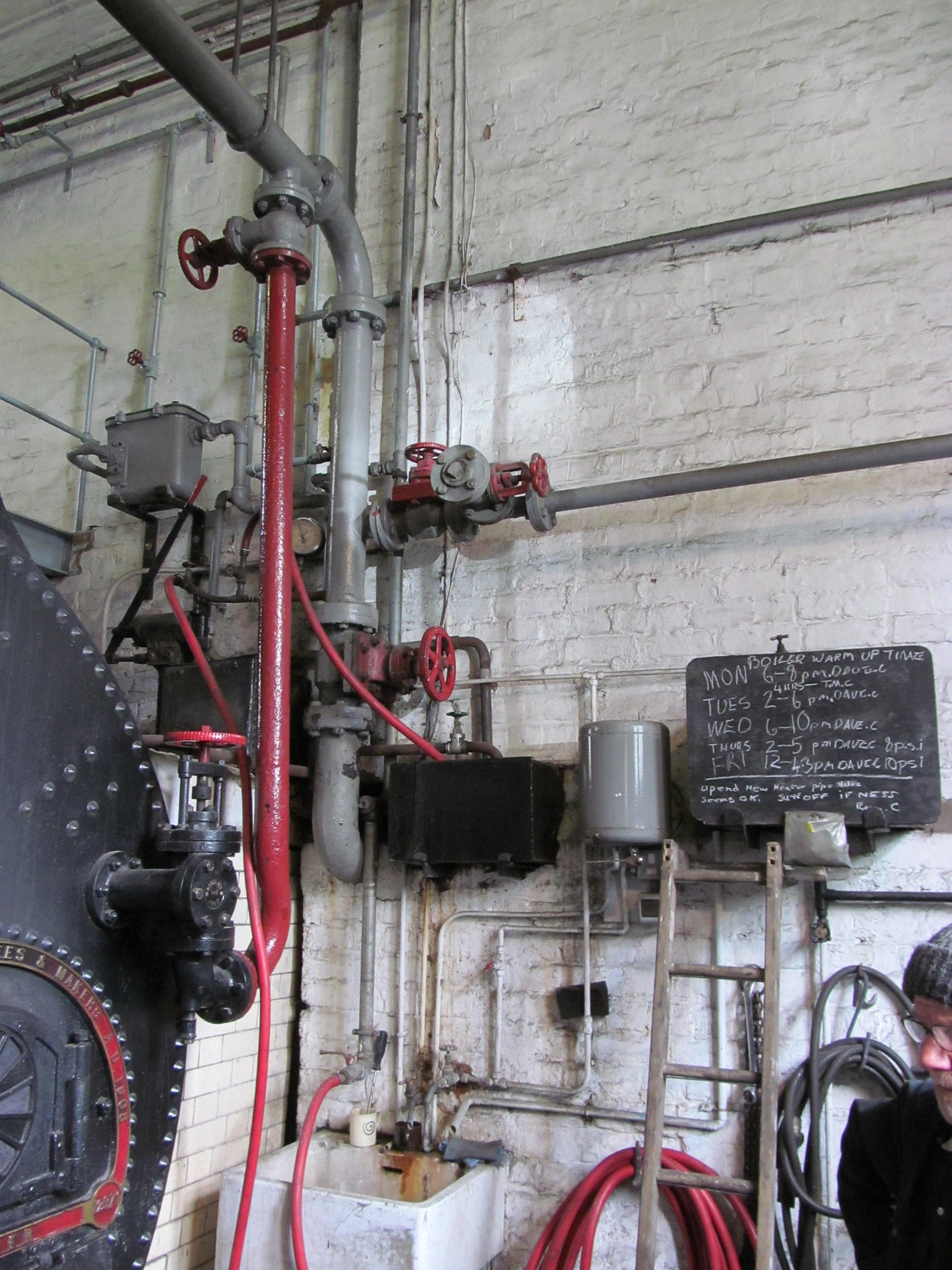
Boiler Plant


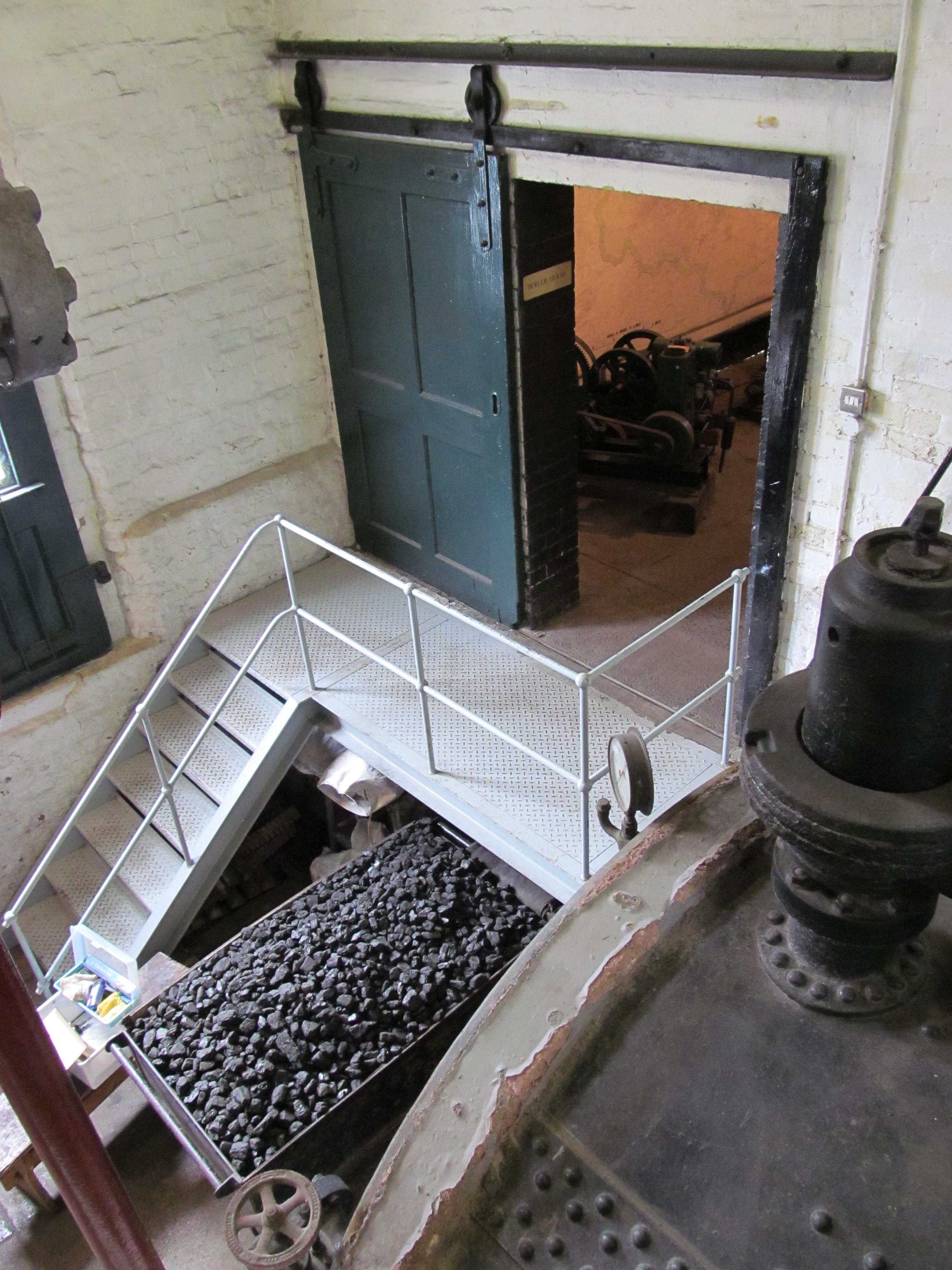


Coal Store

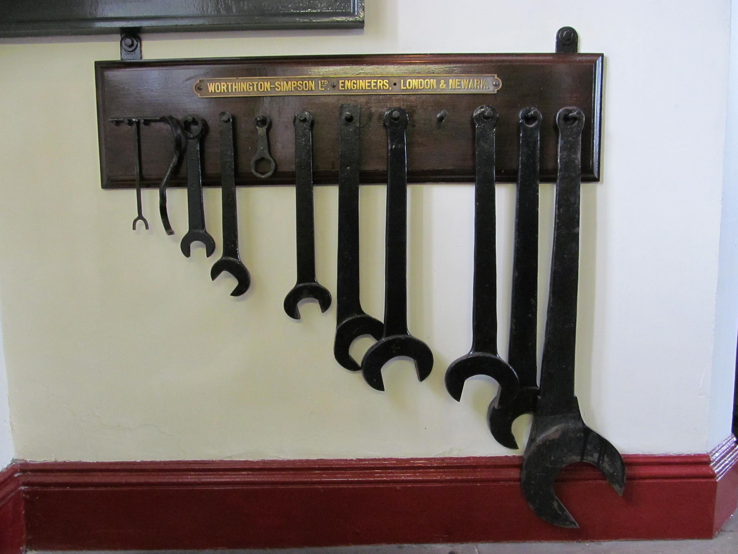
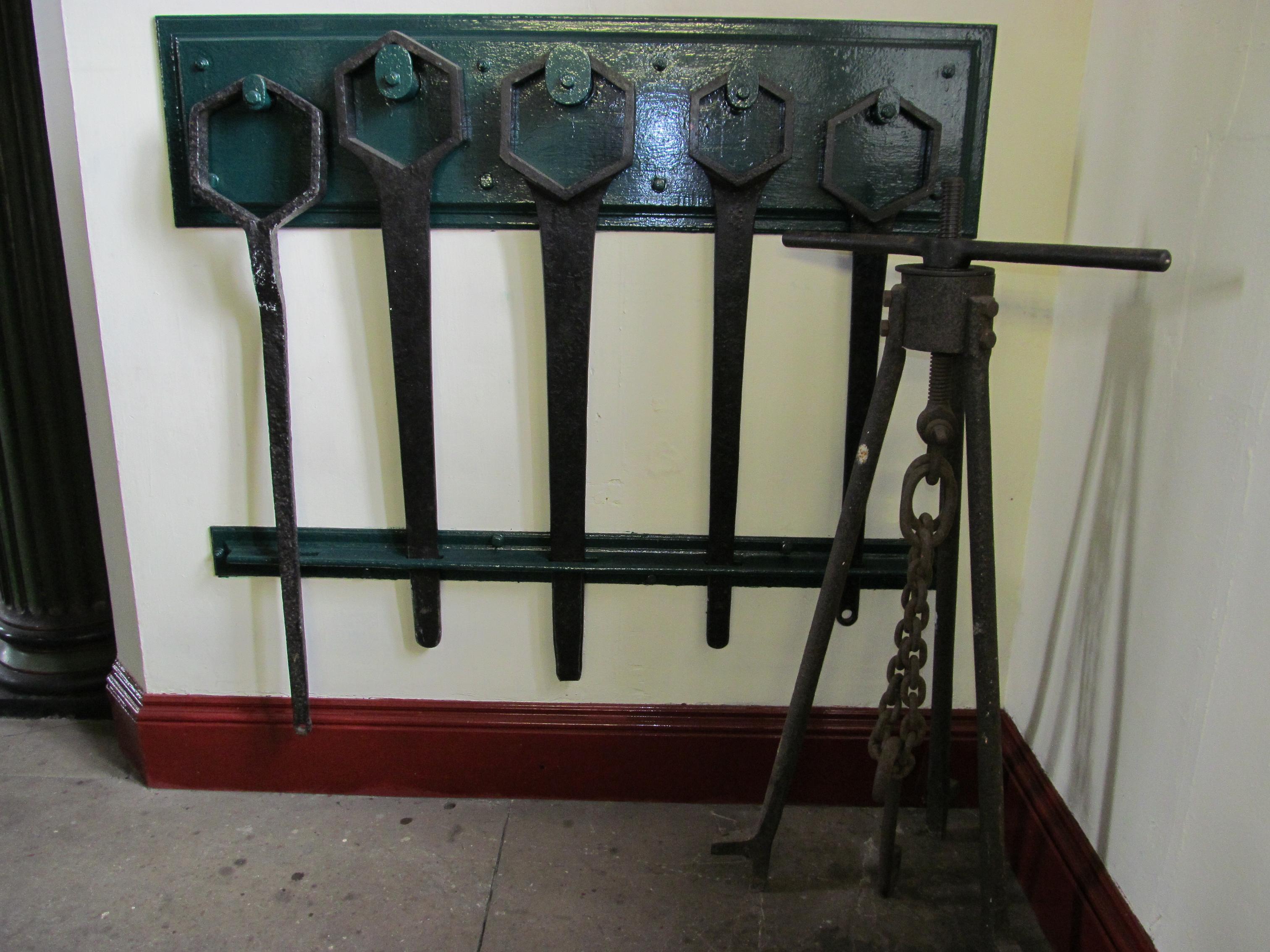
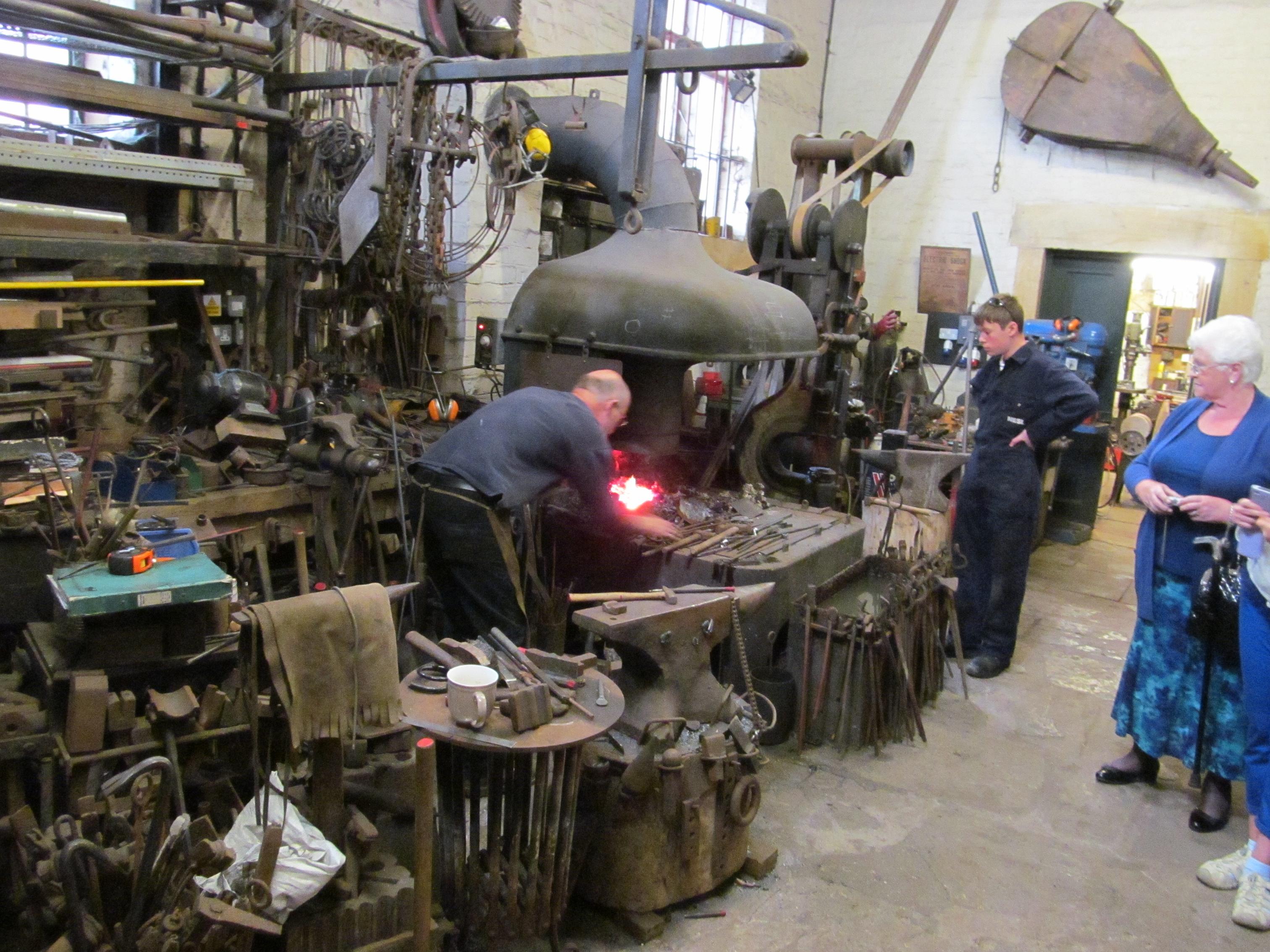
The Blacksmiths
Videos
To Make this post even bulkier here is a load of video footage shot inside the museum largely showing the various parts of the engine at work.
Fossils and Fortunes – Saturday 6th July 2013
Cleveland Ironstone Mining Museum in Skinningrove is holding a heritage day event ‘Fossils and Fortunes’ at the Museum on Saturday 6th July 2013. Talks will include Ages Past, Plant Fossils at Marske Quarry, Alum Folk, Ironstone, Maps and Museums- William Smith, the Rotunda Museum and the Geology of the Yorkshire Coast and Protecting your Earth Heritage. Speakers include locally based specialists including Denis Golding of TVRIGS, Mike Windle (NE Yorkshire Geology Trust), Will Watts (Scarborough Museums Trust), John Waring (TVRIGS), Peter Appleton (Cleveland Ironstone Mining Museum) and Andy Cooper (TVRIGS). All welcome, but spaces limited booking required.
No formal charge, donations will be invited from the audience.
To book or for further information please contact Jean Banwell to book on 01287 642877 or by email jean@ironstonemuseum.co.uk Sandwich lunches can be ordered in advance.
Current Mining Investigations in Skinningrove – Sunday 14th July 2013 14:00-16:00
Join Simon Chapman, amateur industrial archaeologist, for an exploration of the original mine buildings and structures at what is now the Cleveland Ironstone Mining Museum and a tour of the nearby excavation of North Loftus Fan House. Simon, Secretary of the Cleveland Mining Heritage Society, is well known for his publications on the archaeology of the local area and accurate accounts detailing changes in the ironstone mining industry.
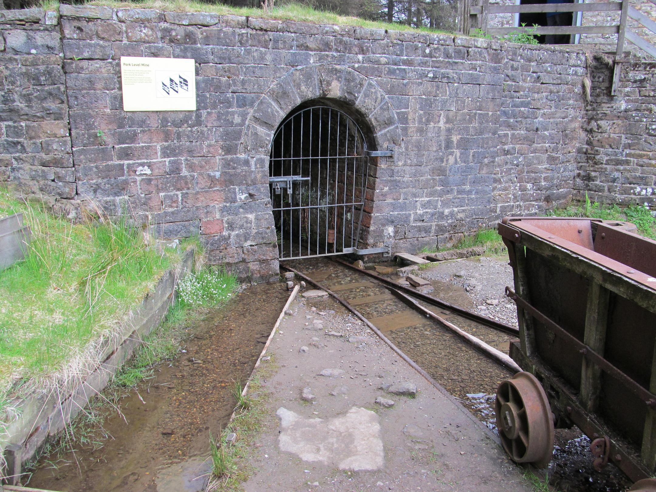
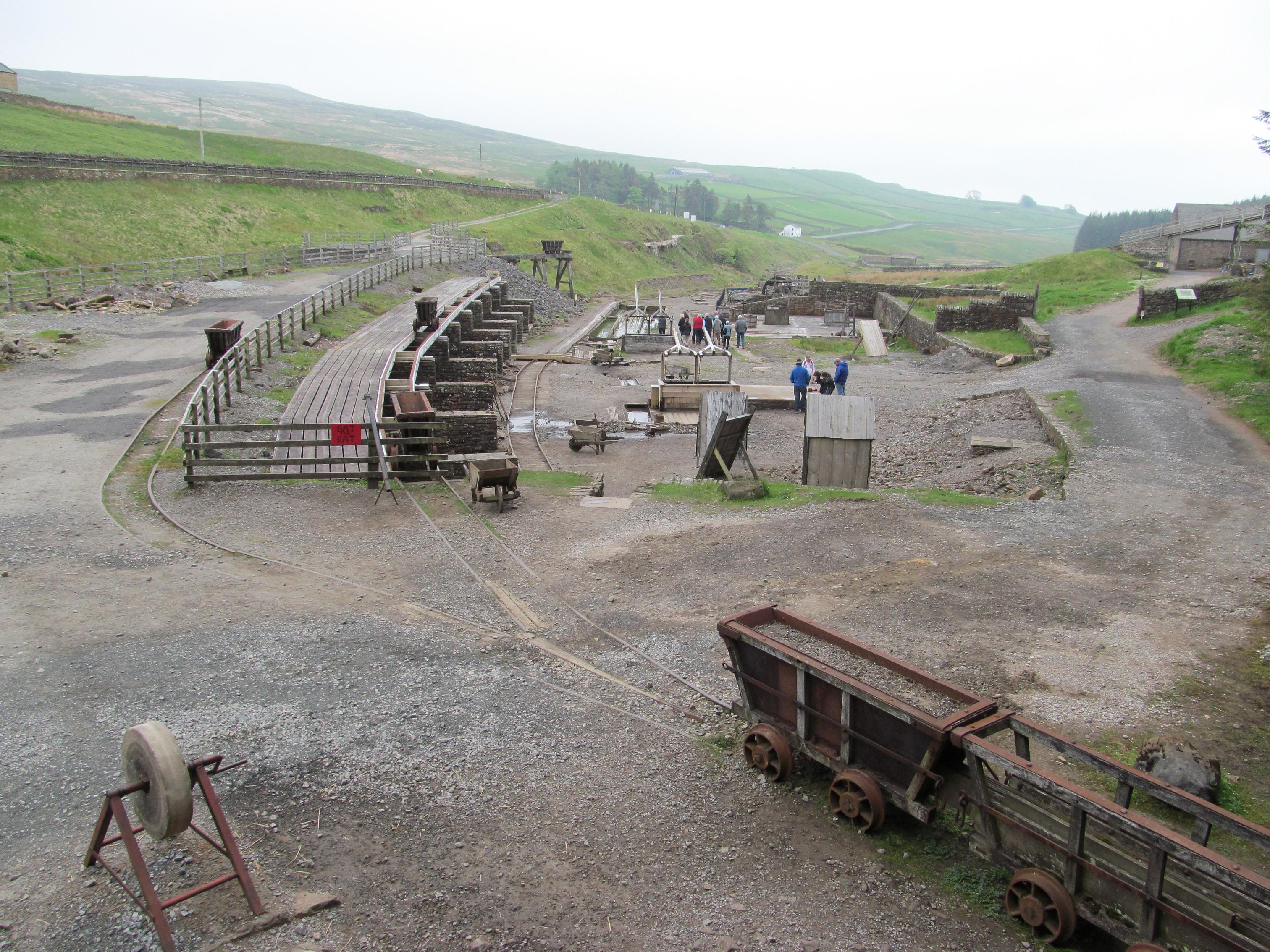
The lead mining museum at Killhope is centered on a Victorian lead mining complex known as Park Level Mine and Park Level Mill.
Park Level Mine was started in 1853 by the WB Lead Company and was driven to gain access to the lead veins in the local area. It was slow work, with the first 500 metres taking five years to cut. Very little ore was found in the first 4 veins but after 20 years a rich ore body was cut which provided work for over 100 miners.
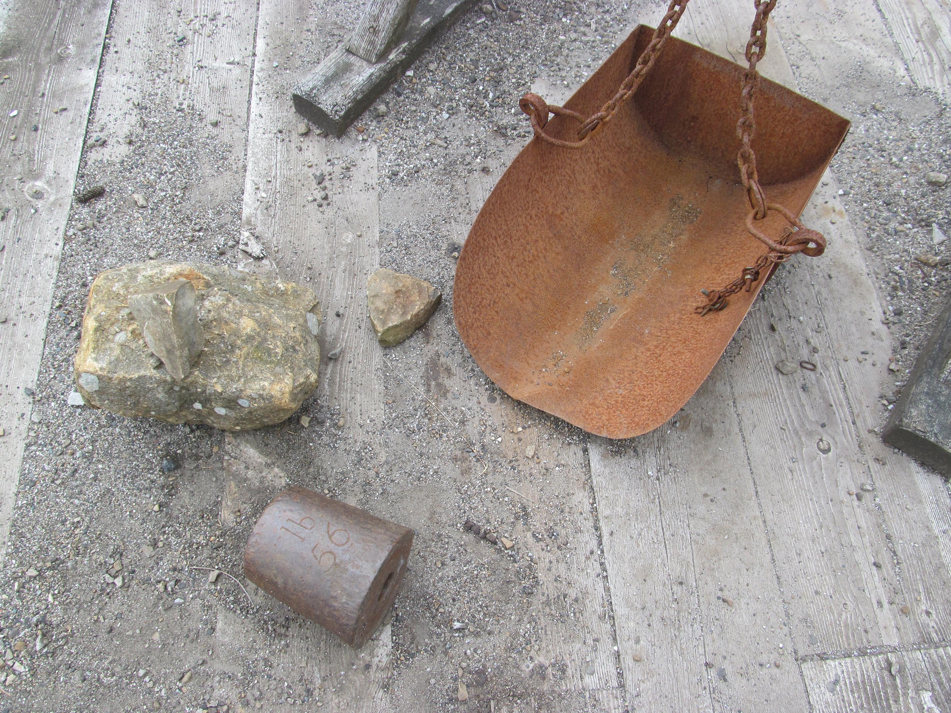
At this time the mine consisted of the usual setup for a lead mining site, you had Park Level where the ‘bouse’ (Ore as it came from the mine mixed with rock and spar) was brought to the surface. It was then tipped into nearby stone built storage hoppers caller bouse teams from where it was then taken to the ‘dressing floor’ for sorting.
We started our tour by looking around the visitor center displays which feature many good examples of local minerals with many historic photos by their side. The center also has an extensive selection of books on local subjects to purchase.

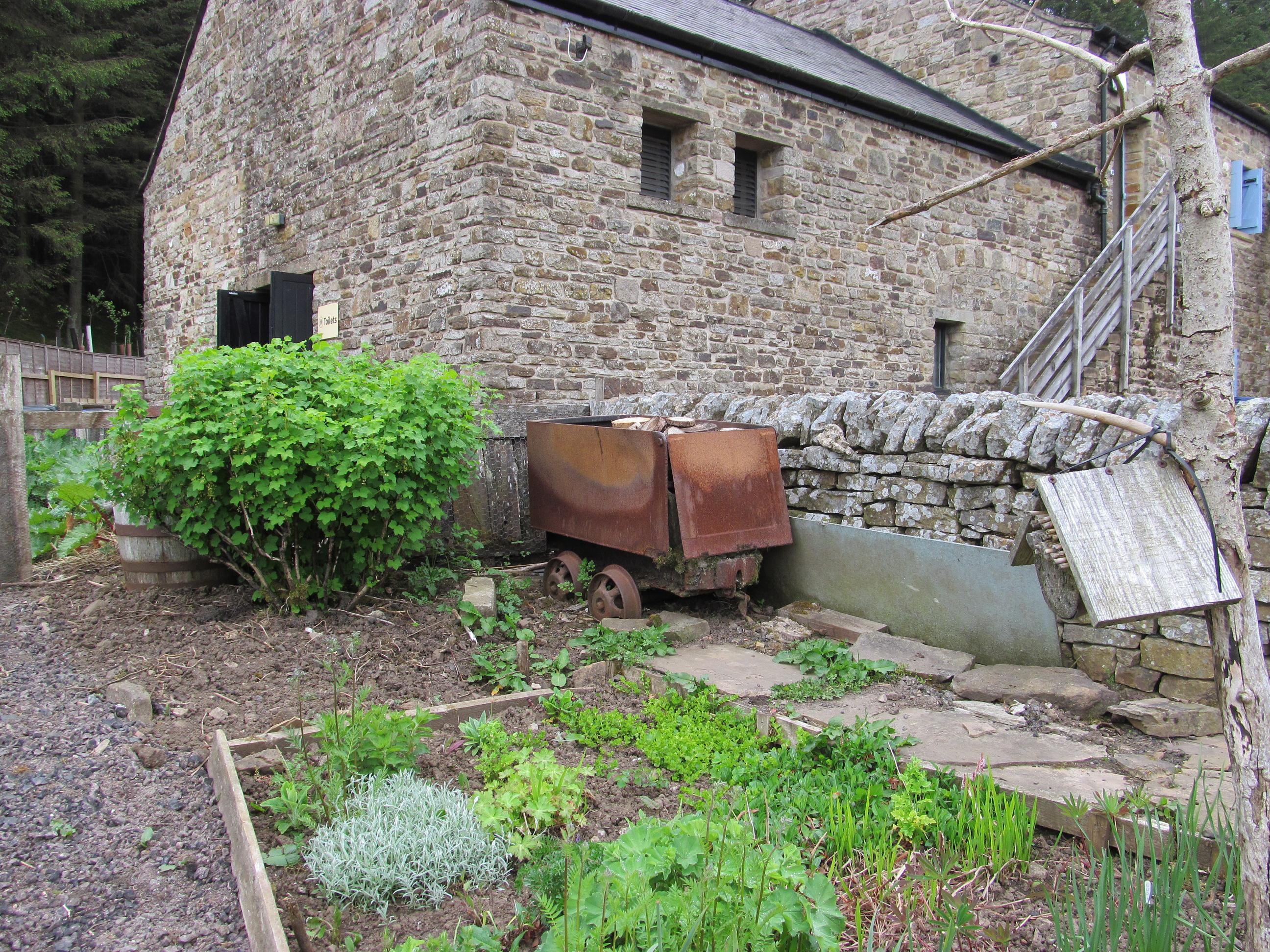
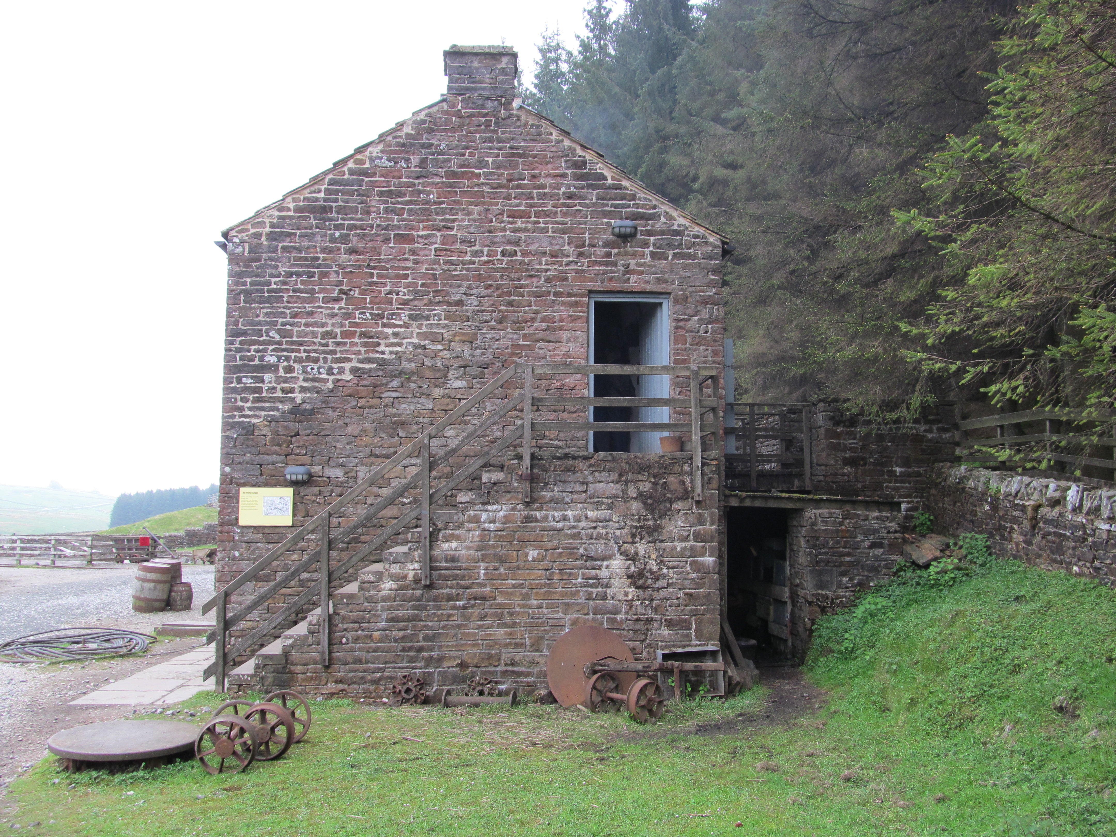
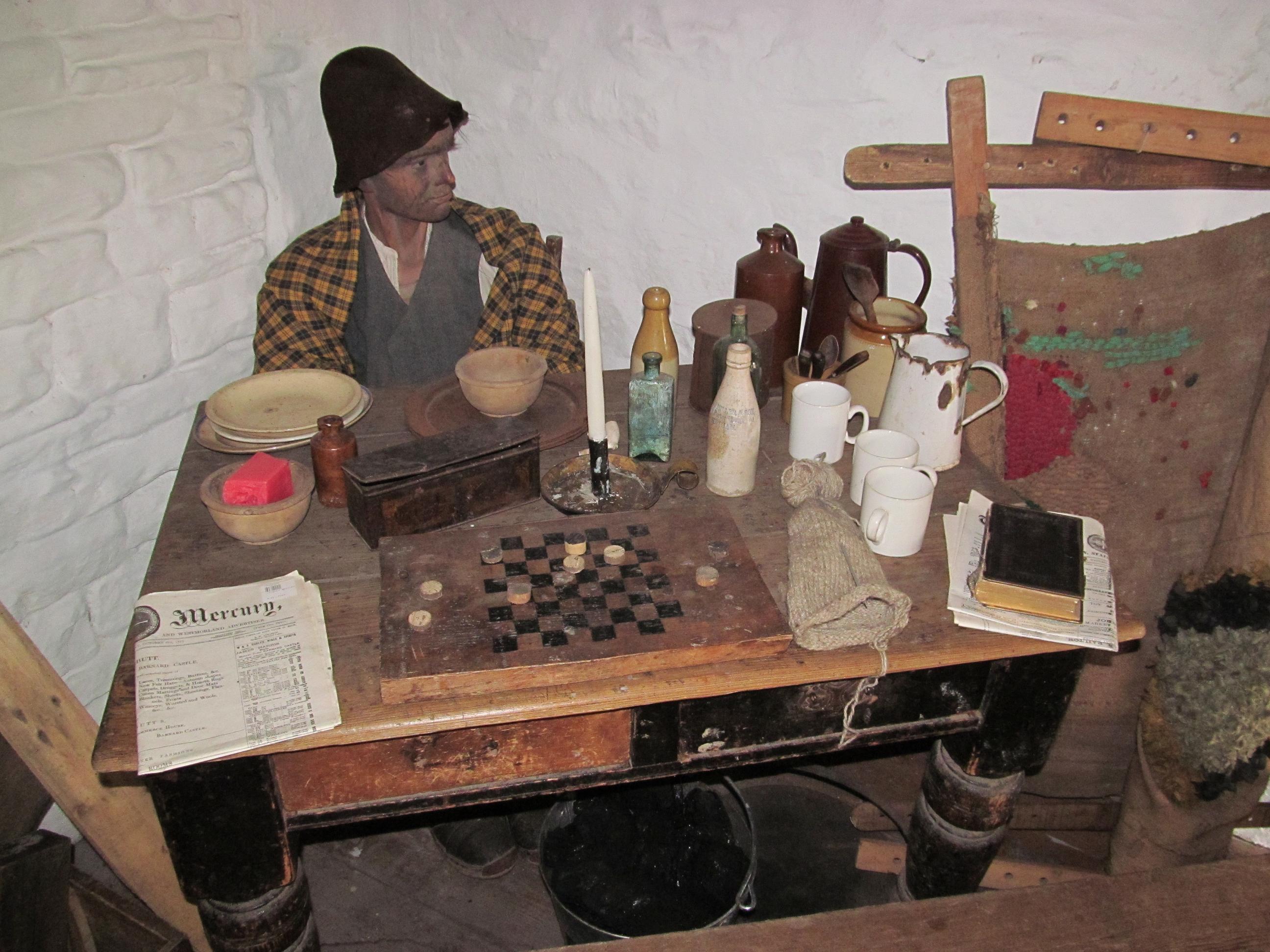
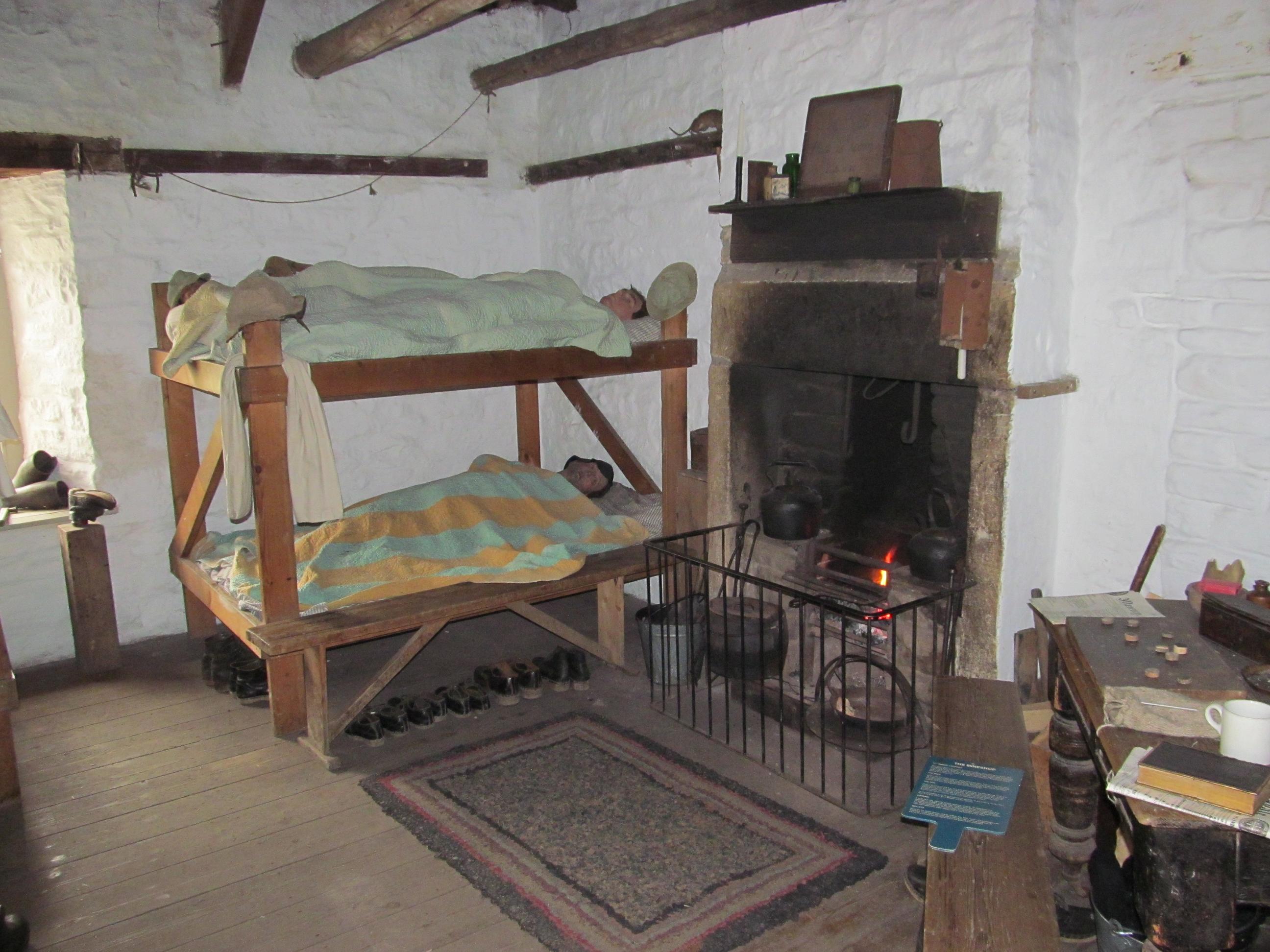
The Mine Shop
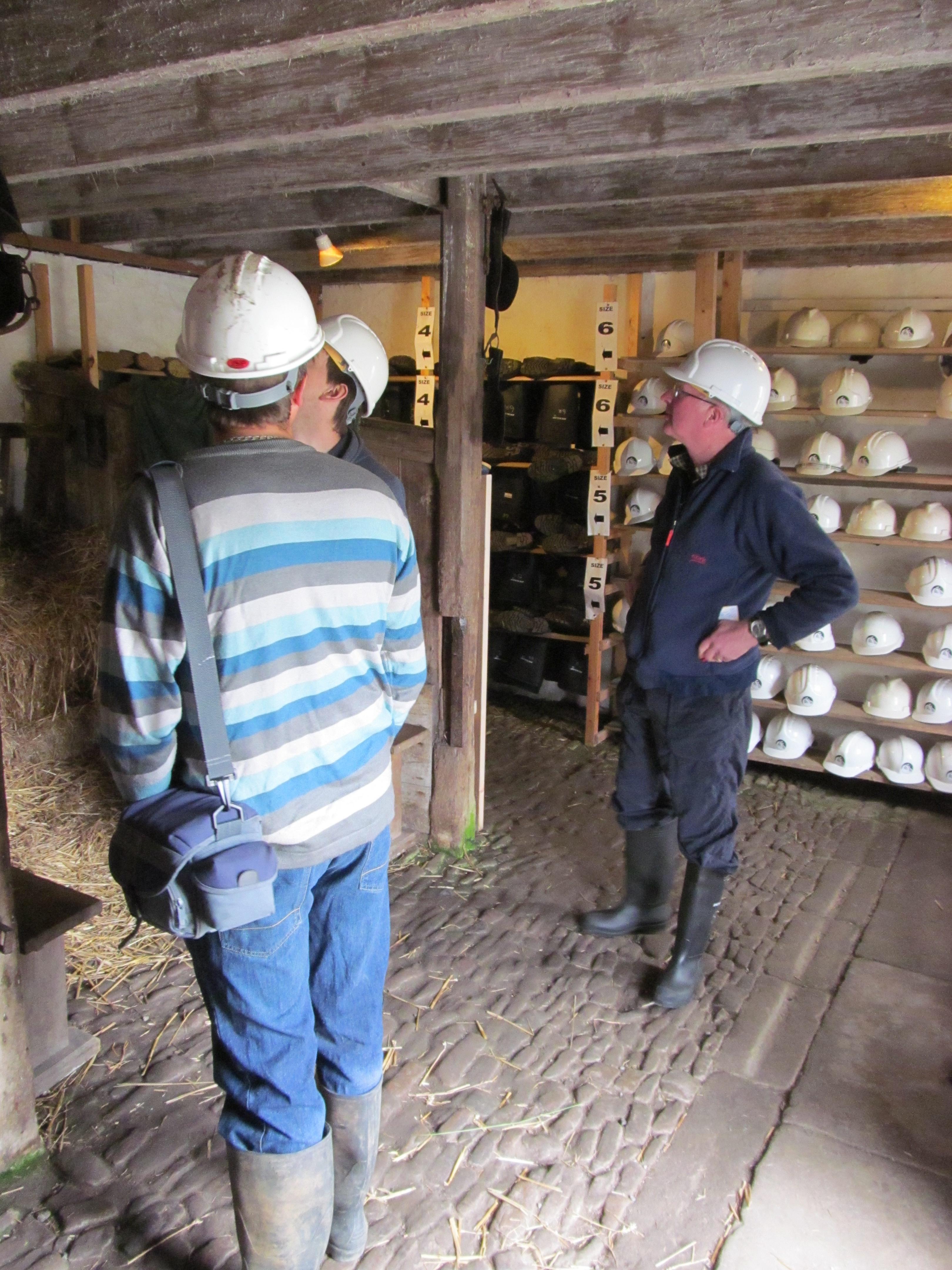
The mine shop consists of the WB Lead Company’s Office, a miners bunkhouse, a Smithy and Stables. After we looked around the mine shop we went into the stables to acquire our wellies and hard hats in preparation for the underground tour of Park Level.


Park Level


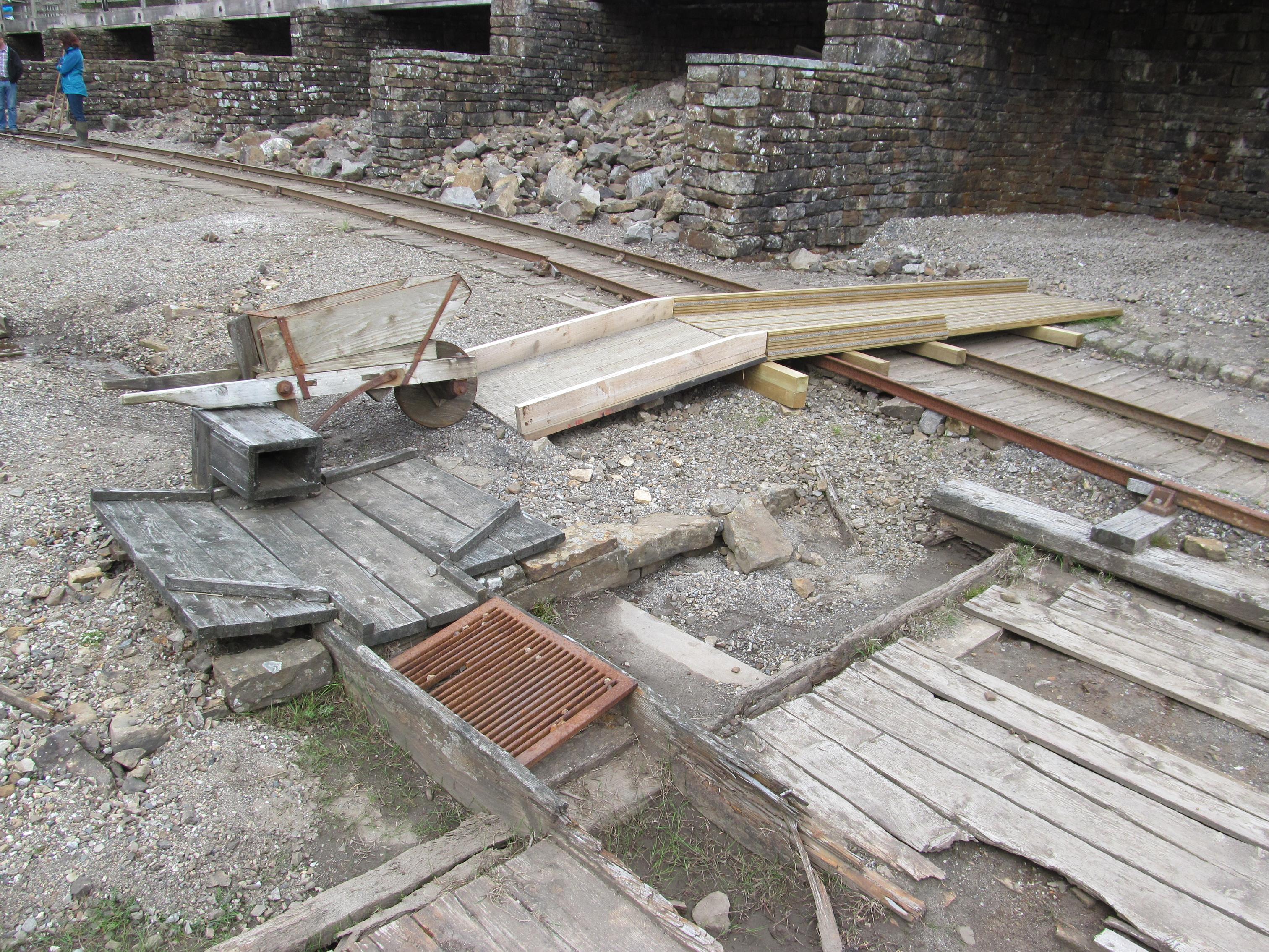
The Washing/Dressing Floor


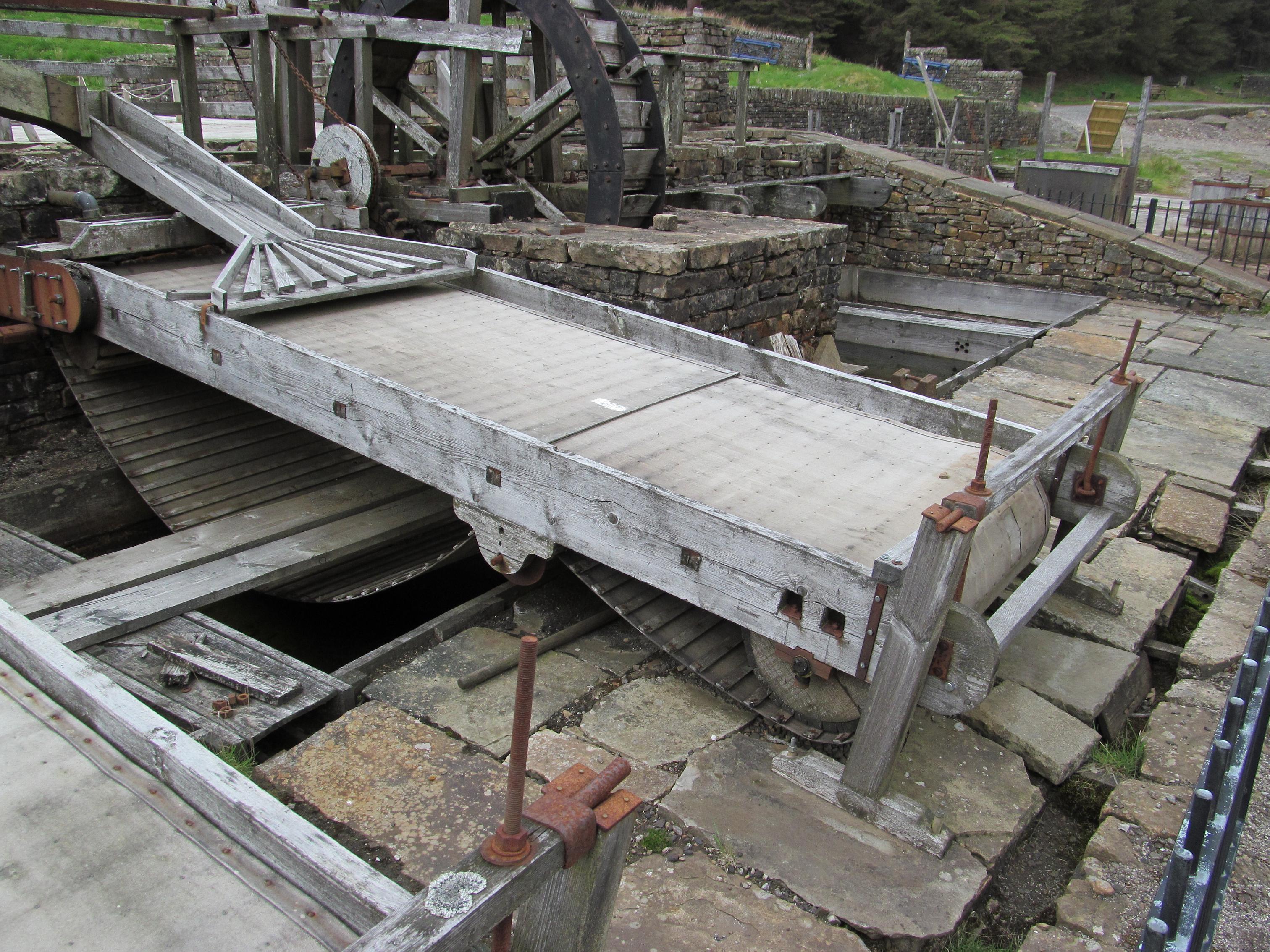
The Brunton Buddles
These four Buddles reprocessed the sludge from the Settling tanks to extract every last particle of ore. Sludge was fed onto the continuous canvas belt and sprayed with water. As the belt traveled upwards, the lighter waste was washed off leaving the lead ore to be carried over the top and deposited in a tank underneath.


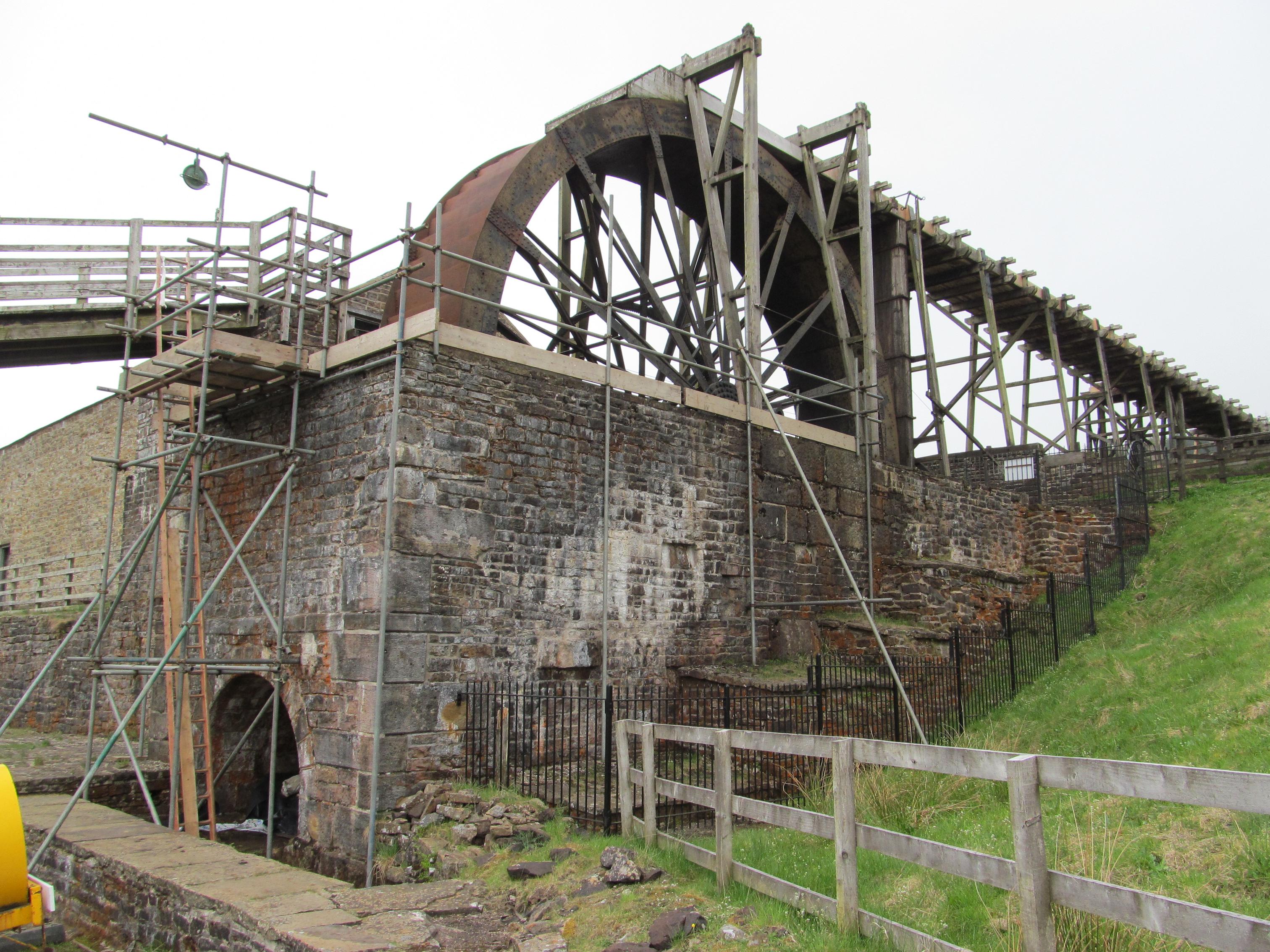
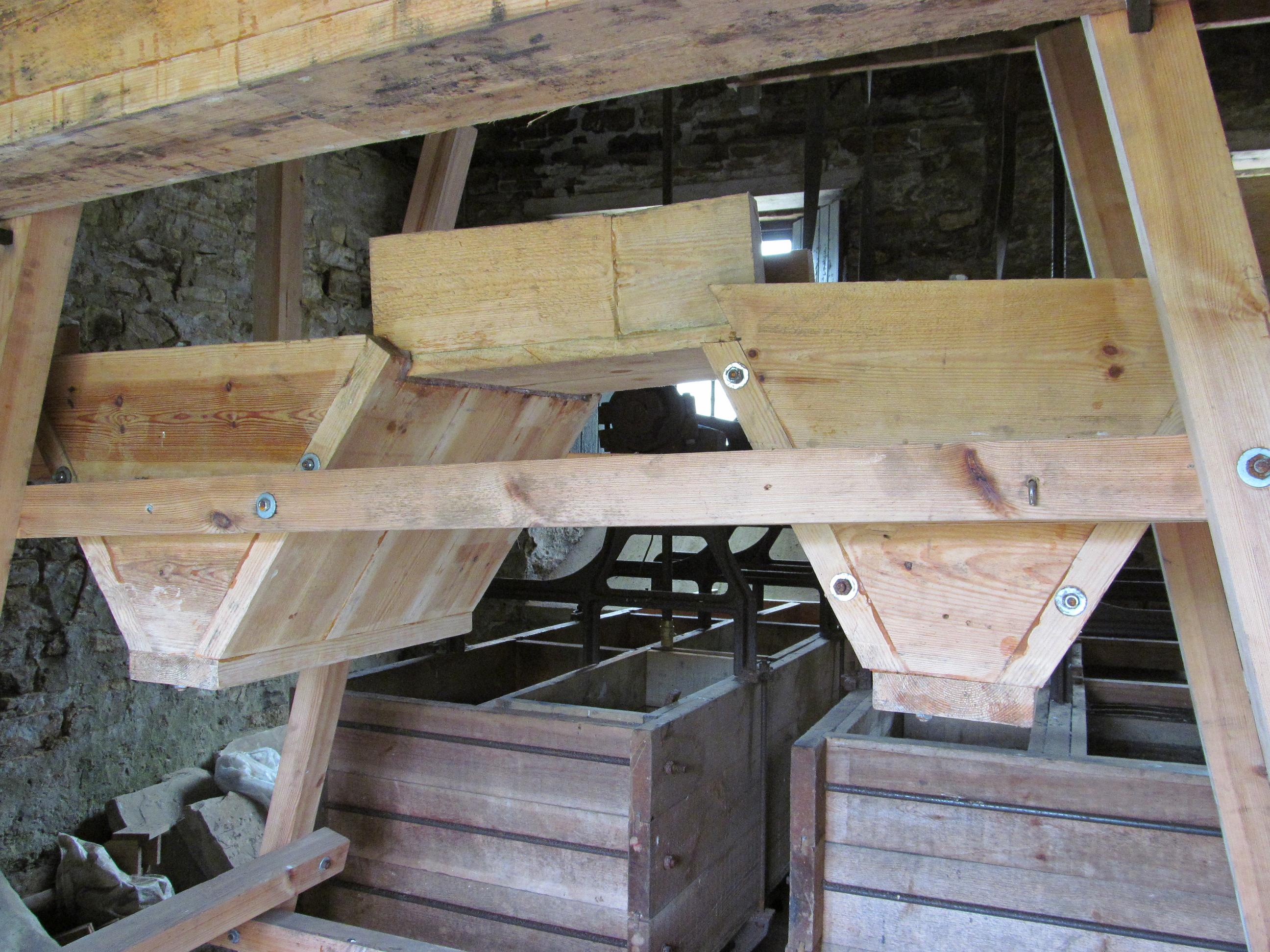
Park Level Mill
Park Level Mill was the last part of Killhope Mine to be built. Men and boys started working there in 1879.
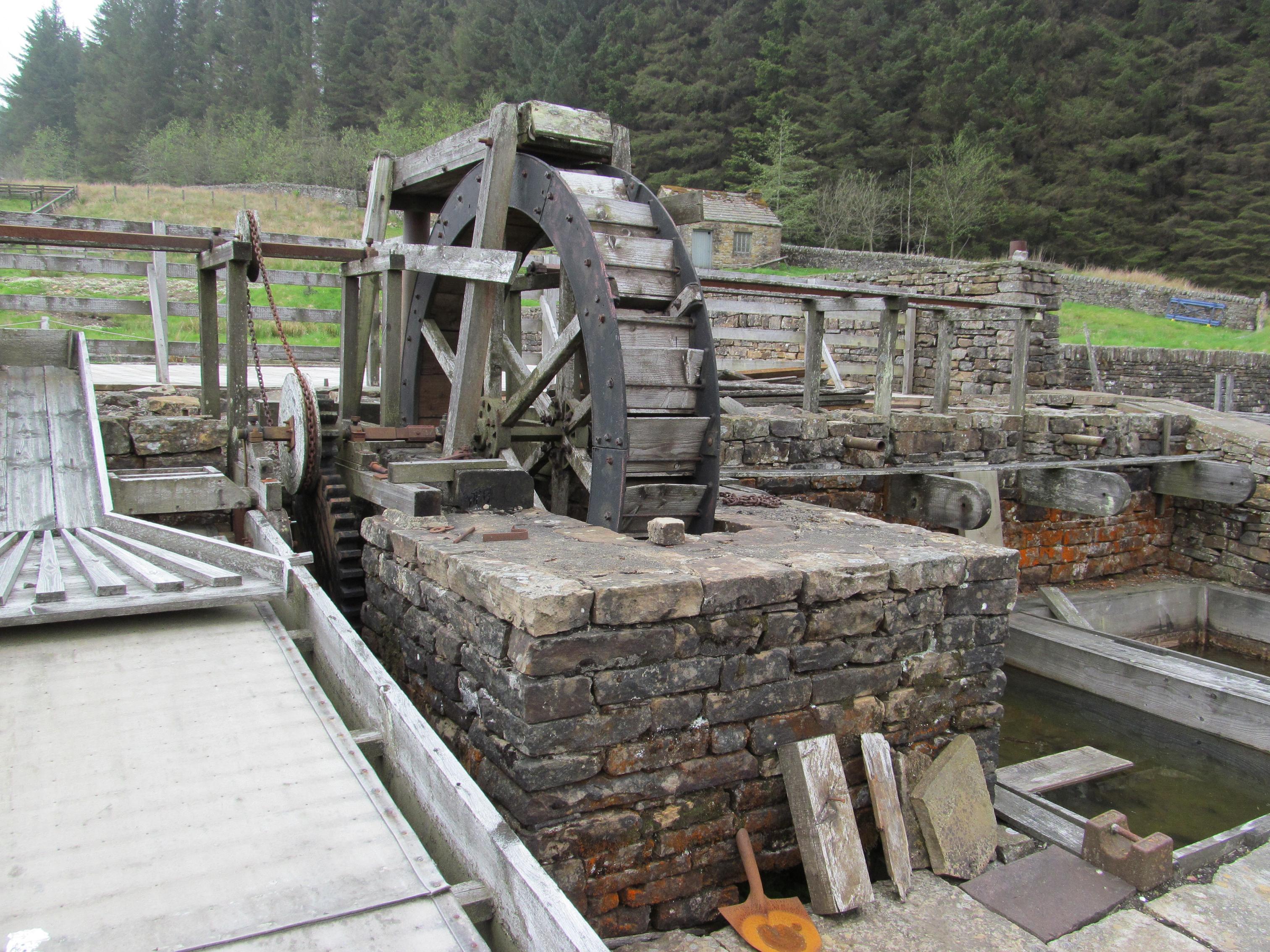
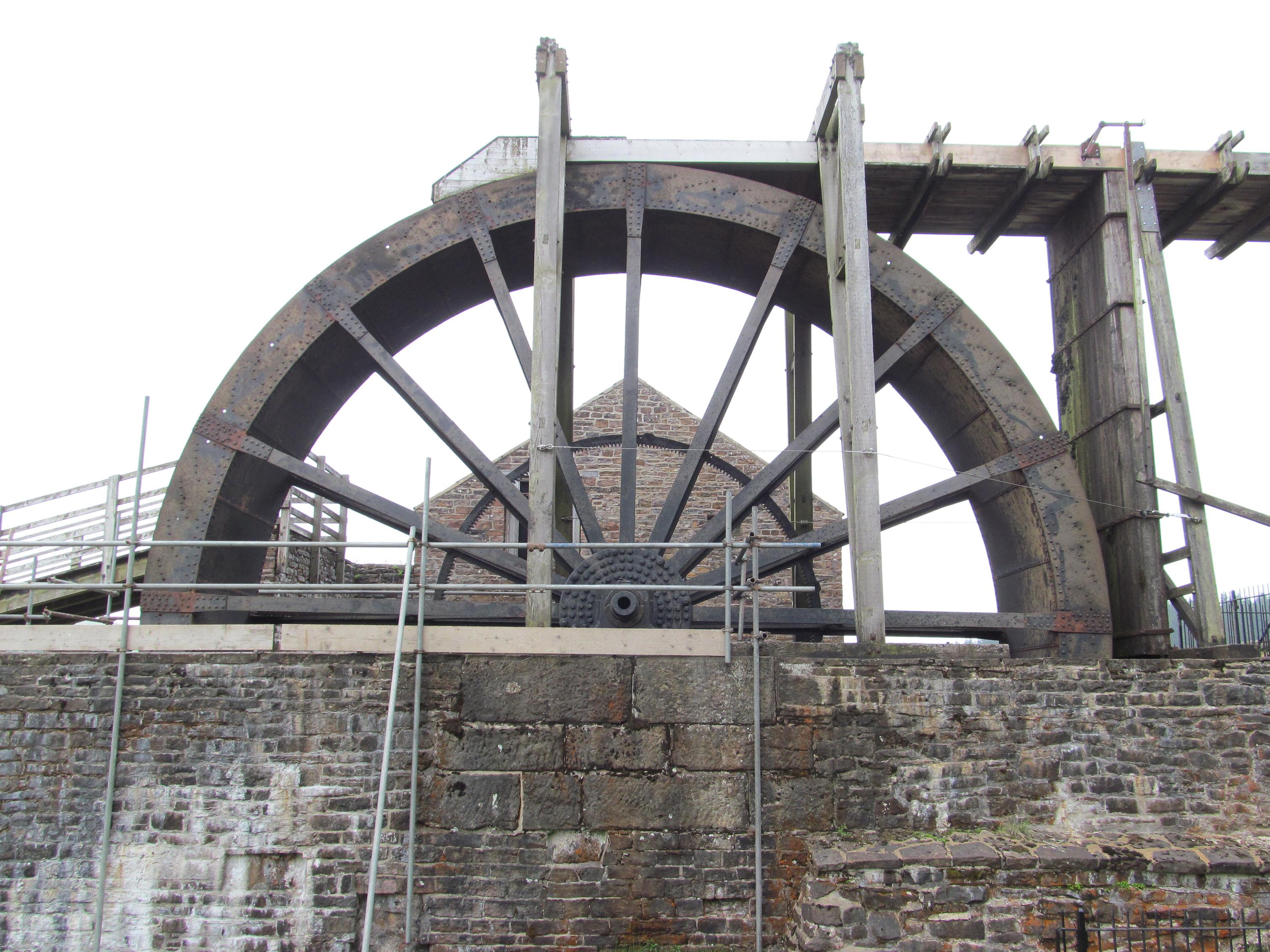
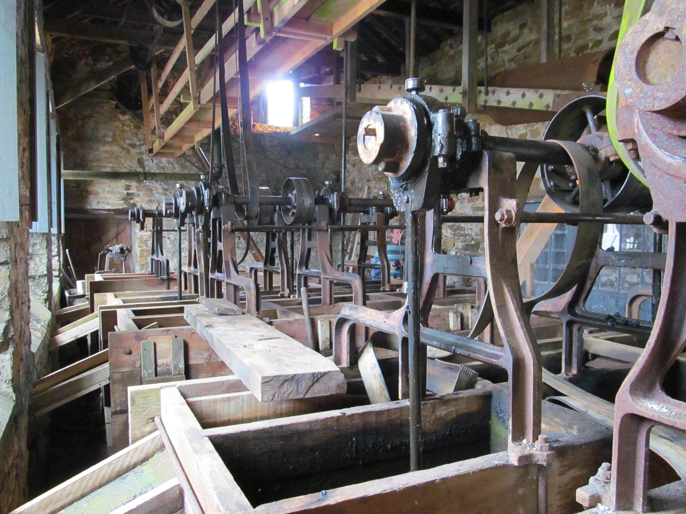
Just as on the washing floor, water and gravity were used to separate lead ore from other unwanted materials.The large waterwheel provided power for the machinery in this building. You can see revolving shafts, pulleys and belts, all driven by the wheel.
The Waterwheel

Railway + Incline To Crusher


The Crusher

The Jigger House


The Large Classifier

The Buddle House

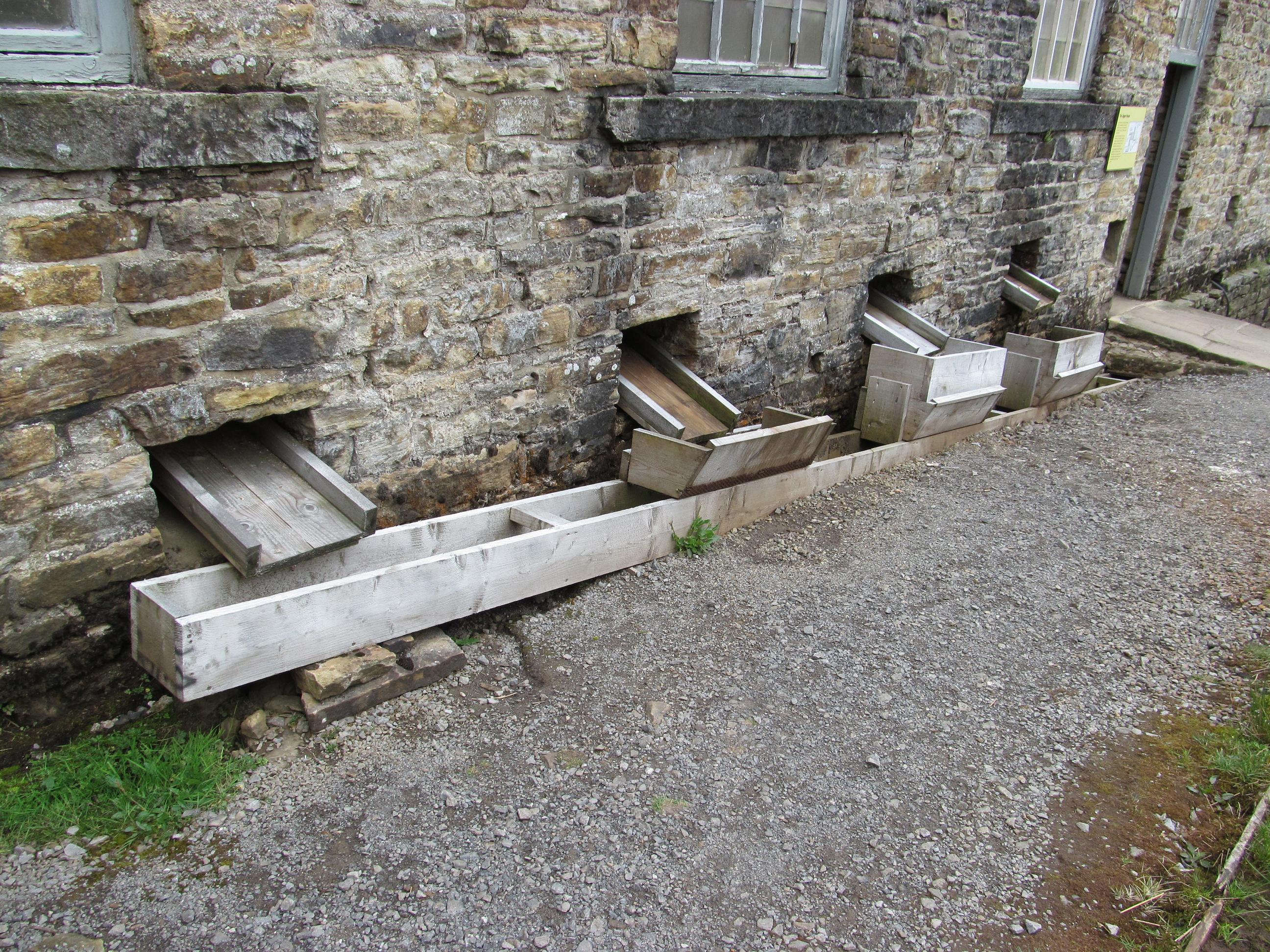
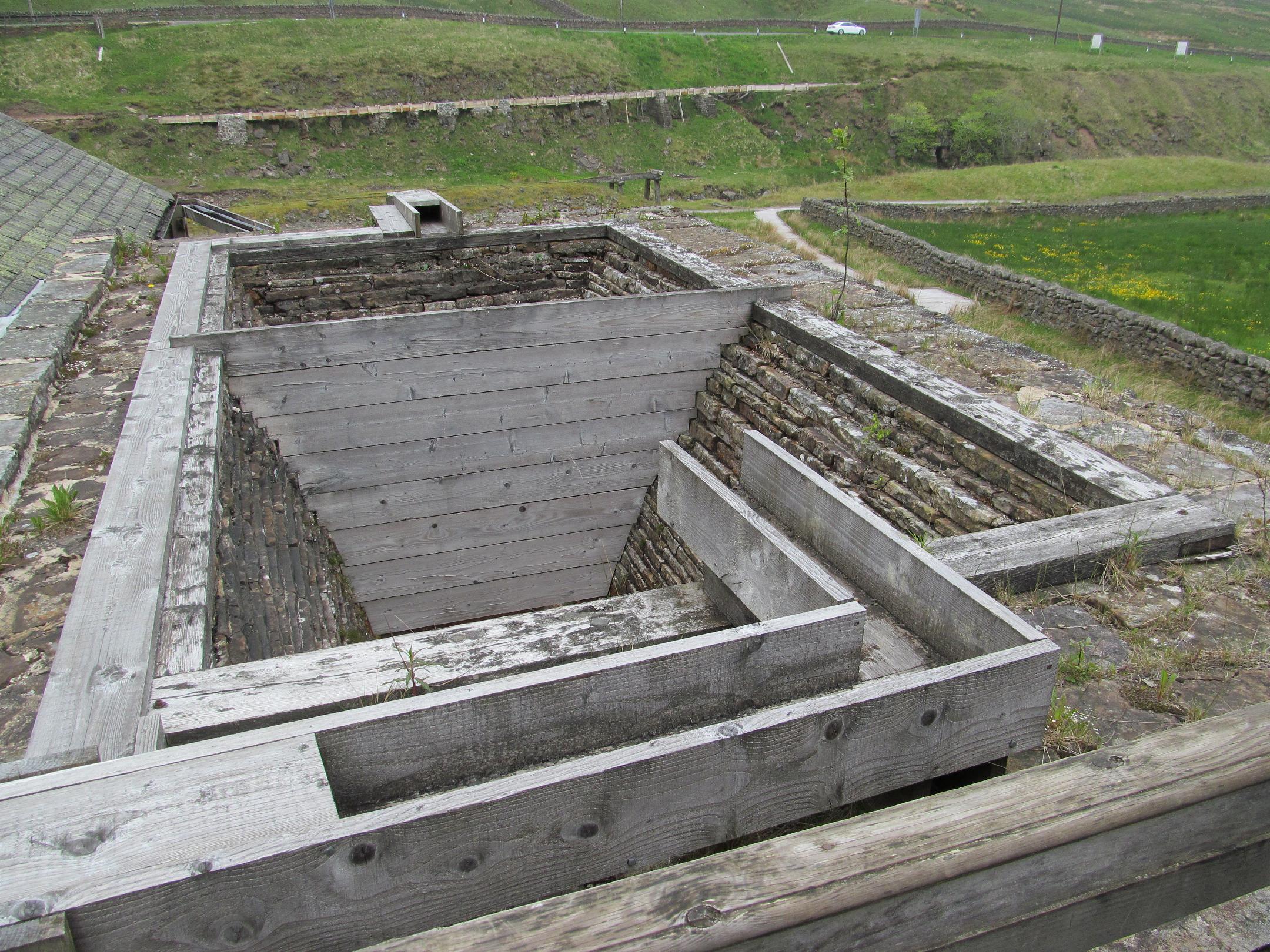
Settling Tanks
To ensure no ore was lost accidentally, all water which had been used in the Jigger and Buddle houses was channeled through these tanks. Suspended solids were allowed to settle and the sediment was then processed on the Brunton Buddles. This work was done by specialist waste washers who were paid for the ore that they recovered.

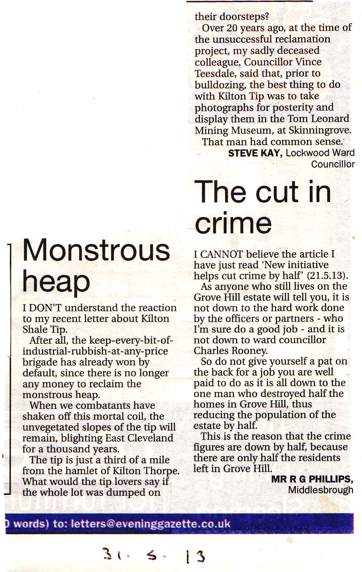
Sadly local Councillors still seem to have very little respect for the efforts of the men and boys of Kilton mine.
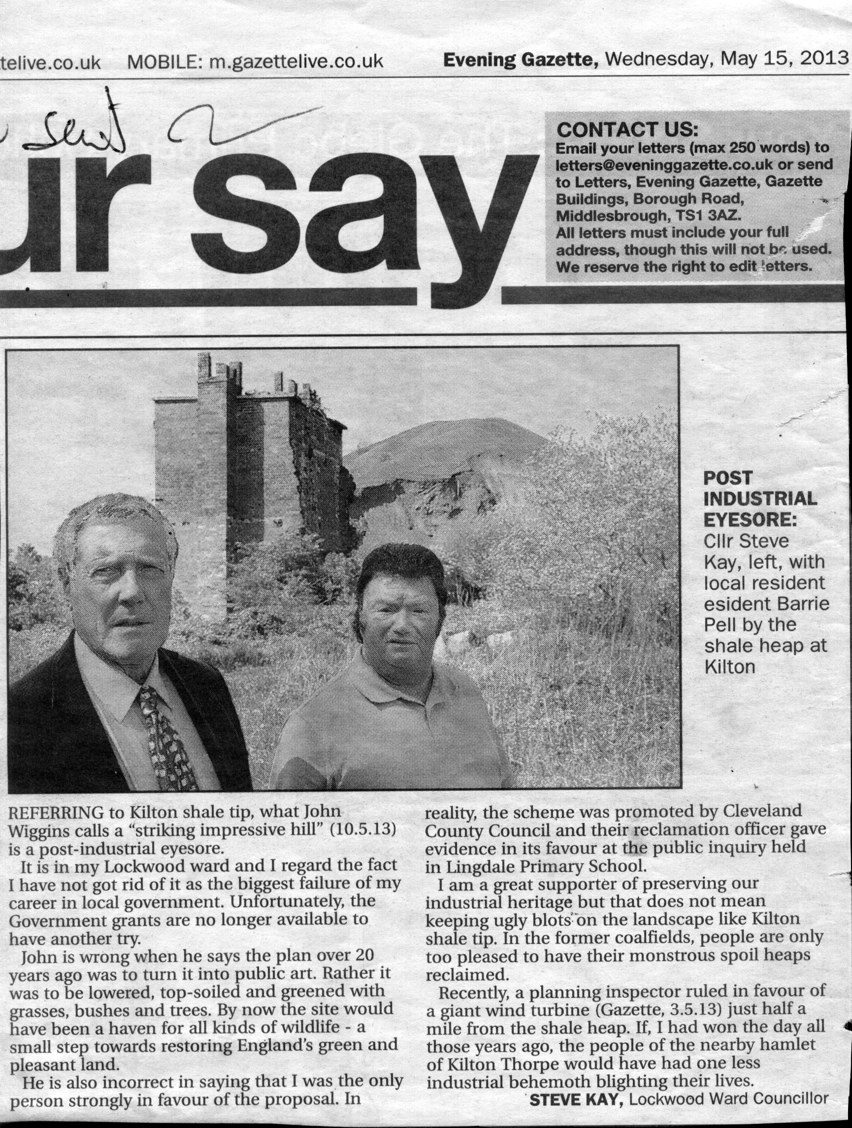
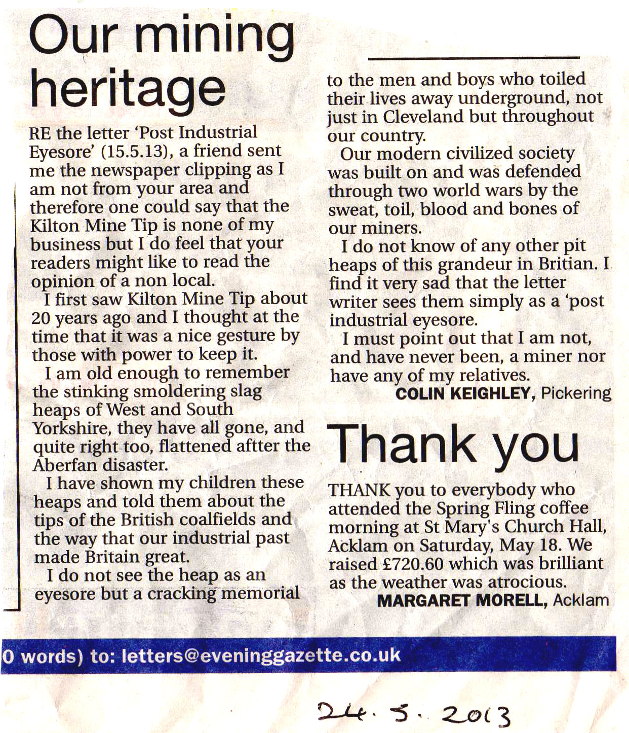
Luckily not everyone feels like they do.
The councillor then resorts to name calling in reply, you would have thought understanding the point of view of others would be a good start for a councillor ?
A couple of pictures from the guided walk to Grinkle Ironstone Mine which was led by Simon Chapman.


Conversation between John Owen and Mr. Noble, Low Garth, Birch Avenue, Sleights, on 1st September 1978.
Mr. Noble worked in ESKDALESIDE MINE for about 3 years, until it closed (in 1915).
He felt sure that Mr. LLOYD was the Manager when he started, but seemed to think that a Mr. Tyreman from Grosmont took over shortly after, and the last Manager came from Lumpsey Mine.
He said that a short distance inside the main drift (below Birtley Farm) there was a ‘landing’ with a brake drum, and from here full tubs were lowered in sets on a self-acting incline, pulling empties up from the tipping place at the railway side. At the tipping place there was no ‘picking belt’, but pieces of shale which could be seen were picked out of the tubs, and if there was much there, the miner responsible was fined.
When he first started, he was ‘Putter’ to George Smith and Mattie Brewster (who lived at Hardstruggle). He said that the empty tubs were pulled as far as the brake drum, then Dick Harland of Grosmont had charge of two ponies, and would pull the empties to the ‘flat.’ From here, he and the other Putters would each get a single tub and push it to the pair of miners they were responsible to, and when filled, would push the full tub back to the flat.
He said a full tub would hold about 10½ cwts but could hold slightly more when the roof was high enough to permit loading the tub above the rim.
The ‘main road’ was termed the “gangway”, and roof support on this was by heavy planks about 9 ins. Wide and 2 ins. Thick pitched about 2 ft. apart across the width of the roof. These planks were named “crowntrees” and were each supported by a prop under each end.
The men he worked for encouraged him to drill, etc., and to learn to be a miner, so long before he had completed 2 years he asked to be allowed to work the stone. The Manager reluctantly allowed him to work a place on his own, at the Hardstruggle end of the mine. He said this drift was then open for access.
While putting, his miners were employed on the LONGWALL, but he couldn’t remember much about this. He said it looked a long way from where he worked “down to the low end.” Questioned, he implied the seam noticeably dipped along its length. He said that when a miner had prepared to fire a shot, he would yell “Fire” at the top of his voice, then wait for all the men to clear the longwall before lighting the squib.
When working his own place, he said that he would turn away a place from the main road, starting the place just broad enough to get a tub through. From this point, the entry was steadily widened. He believed the bord at full width was 30 ft. across, but was very unsure about this. Props with a wooden cap placed across the top of each were used for support.
He said the seam was about 3 ft. 6 ins thick, with about 4 ins. Of shale in the middle, and the top block was about 12 ins thick and composed of good heavy ironstone. Shot holes were drilled in the bottom block and the shale and top block were wedged down. About 12 ins thickness of shale was lifted from the floor in solid blocks called “coggers” to make dry walls along the working place, and small shale was thrown behind. He said the deputies would come in periodically to ‘draw’ the props near these dry walls, and the roof would ‘bend’ onto the walls. Props used were 4 ft. 6 ins long. (I could not be certain of how these walls were placed, nor could he explain).
He said that rotary hand-drills were used, as in the Main Seam. Owing to numerous small ‘backs’ in the stone he seldom used the longer (3’-6”) drill and before loading with black powder, the scraper was used to try to feel any backs. When ore was found, the hole was stemmed with shale as far as the ‘back’ before putting in the powder. He said the ventilation was very poor and a shot fired into a ‘back’ produced a great deal of smoke which took a long time to clear. He agreed that a hole was drilled at an angle to the face. In a low, wet place in the mine, one miner used to get as much stone as possible using wedges rather than powder.
In pillar working (he stressed this) he was paid 2/4 per ton and earned about £2 per week average (i.e. 15 tons per week). He believes he only worked 5 days a week.
Candles were used for lighting, with (he thinks) oil lamps by the officials. He cannot remember his candles going out in stythe, but blamed powder smoke entirely for poor ventilation.
He believes about 50 men total were employed with a Manager and perhaps 6 deputies, but no Overman. There were few accidents and on reflection he enjoyed working there!